![]() The content of any article might be expanded / improved in the future - revisit it sometimes.
The content of any article might be expanded / improved in the future - revisit it sometimes.
![]() Seen a mistake? Know something that isn't written? Edit and change this article yourself!
Seen a mistake? Know something that isn't written? Edit and change this article yourself!
![]() Some images in the article (if present) can be enlarged by clicking on them.
Some images in the article (if present) can be enlarged by clicking on them.
Contents
Introduction
If you have a winch it probably sits out on the front bumper in all weathers, taking the salt spray from the road, the mud and water from off-roading and is finally asked to haul the heaviest of Land Rovers out of the mud once a year. Here is your big moment as a Suzuki owner and......the winch doesn’t work, or in my case it does work but sounds like a tumble dryer full of stones. How embarrassing!
Therefore it is good practice to strip and re-grease your winch every year.
I have just done mine and thought I would do a another write up. However this difficult as every winch is slightly different, this article shows the strip of a Champion 8000 winch, yours may well be different but the principles are probably the same.
The task of stripping a winch is actually quite easy, the difficulty is remembering where all the little bits go!
Disassembly
Dismounting the winch
- First remove the winch cable itself, this makes it easier to handle the winch.
- Now record where all the connections go.
- Depending on how your winch is fitted you may have to do this before you unbolt the main winch mounting bolts from the car.
- You may have a remote solenoid (like mine) or a solenoid mounted on the motor or a bridge solenoid.
- The solenoid is the black box of electronics that controls the winch.
- If it is remote, then you just have to disconnect the leads running to the motor.
- If it is motor or bridge mounted, then you have to disconnect the wires to the solenoid and then remove the solenoid pack (probably once the unit is removed from the car).
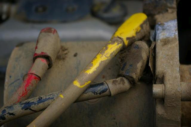
- The motor will probably have an earth lead under the motor running from the solenoid (I know mine is coloured red!).
- A sensible installation would have this in black!
- On the other side of the motor will be the power and field connections also running from the solenoid.
- These will be colour coded and WILL be different to mine shown in the picture.
- Therefore, make a note of where yours connect to.
- Also be very careful undoing these.
- The other end of the stud inside the motor is connected to a wire.
- If the stud rotates, it will break the wire.
- Therefore, make sure as you undo the nut securing the cable, that the stud is held fast and is not allowed to rotate.
- With the motor electrics disconnected, you can probably remove the winch from the vehicle.
- With the winch on the floor, you can now separate it into the major components:
- the motor
- the drum
- the gear box
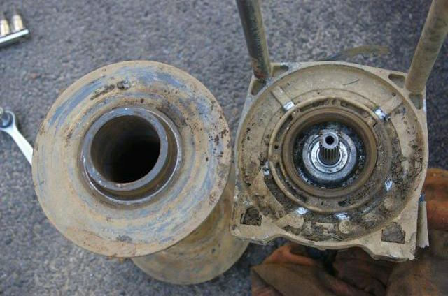
- Winches are held together either by a solenoid bridge mounted across the top of the drum, or by heavy duty threaded bars.
- In the previous picture you can see the end of one of these bars to the bottom right of the picture.
- Undo the hex socket headed bolts holding these bars (or the solenoid bridge mount) in place.
Disassembling the main parts of the winch
- Carefully part the drum, motor and gear box.
- At this point some parts may fall out.
- The first is a hex shaped bar that comes out of the centre of the drum and goes to the gear box.
- If this has not fallen out, then gently pull it out and put it aside.
- The other part is a cup that sits on the end of the motor (inside the drum) and connects to the brake mechanism in the drum.
- Again look closely at how the cup fits and put it to one side.
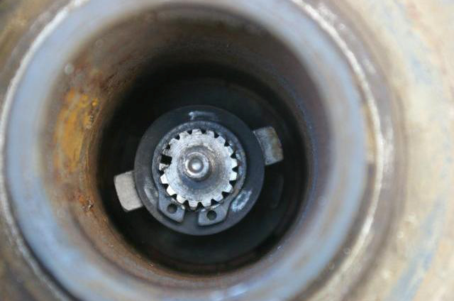
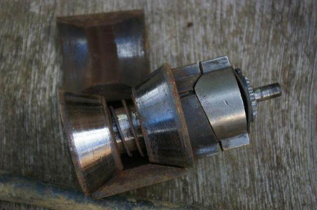
- Inside the drum will be a cone brake (if your winch has a drum brake – more expensive winches have the brake in the gear box).
- Typically this will be stuck inside the drum (this picture shows mine).
- Note the dog ears that match up with the cup on the end of the motor that you have just removed.
- You will need to gently drive the brake mechanism out if it is stuck.
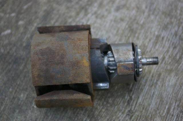
- This picture shows my brake once it is removed.
- Note: you can usually only drive it out in one direction.
- But helpfully I can not remember which direction that is!
- There is a step machined inside the drum to stop it going the other way.
- The cone brake is a simple cam mechanism that pushes the three loose brake shoes out against the drum.
- This needs a simple clean up, lubrication of the moving parts (not the shoes!) and putting aside ready for re-assembly.
- You should also clean the braking surface down inside the drum, which will be rough and rusted if your brakes had stuck (not an easy task).
- Now it's the time to tackle the gear box.
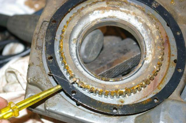
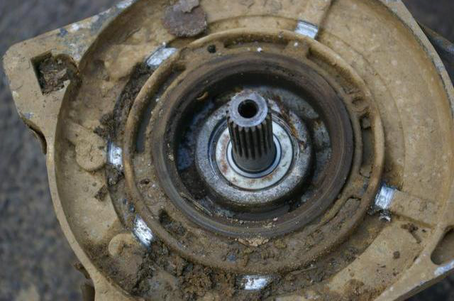
- The gear box will be held to the drum end plate by some small screws.
- In my case these are hex socket headed bolts.
- On the back of the end plate is a seal which should not be lost!
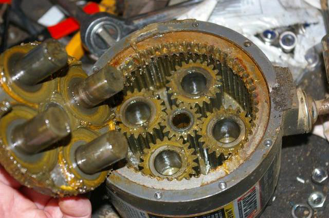
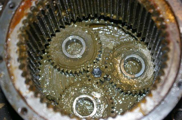
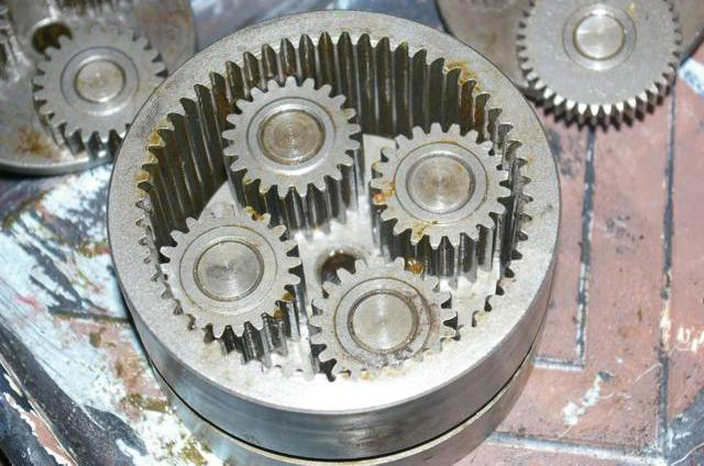
- The gear box consists of layers of epicyclic gears built inside the clutch ring.
- The clutch ring slides and locks the outer edge of the gears, forcing them to do their work.
- Each layer needs to be lifted out and cleaned.
- First release the clutch ring by removing the clutch lever from the casing.
- Mine was secured with a small hex socket head bolt.
- With the bolt removed, the clutch lever pulls out.
Disassembling the gear sets
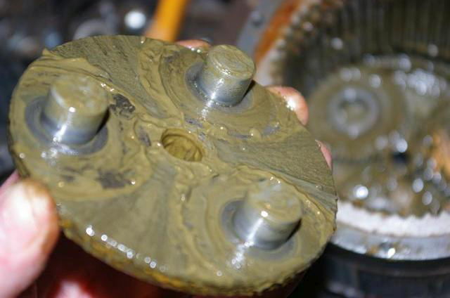
- Now you can start lifting the gear sets out.
- The sets are built up in layers with the strongest first (counting from the top!).
- Each layer consists of a plate with “pegs” and a set of gears.
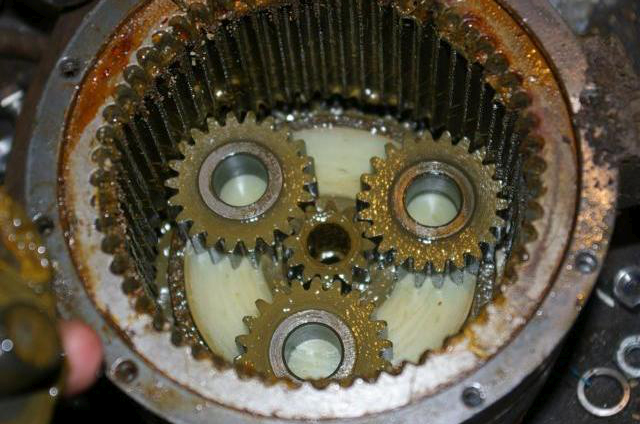
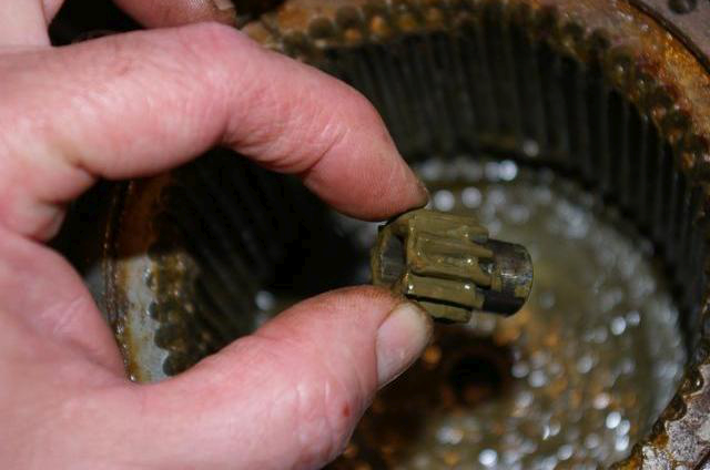
- The pictures below show the progress through the layers.
- The final layer also has a small loose gear that sits at the very bottom and takes in the drive from the hex shaft that leads from the drum.
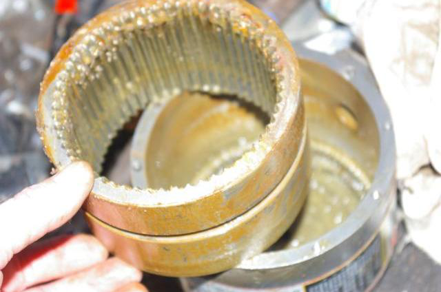
- At this point, the clutch ring can be slided out of the casing.
Cleaning
- The next stage is cleaning.
- Clean all the gears, plates, clutch ring and casing.
- Remove all the old grease and gunge.
- I used a paraffin based cleaner and a paint brush.
Re-assembly
- The re-assembly of the gear box is actually quite straight forward.
- Whilst I dismantled each layer with it still inside the gear box (to keep it all together), I found the best re-assembly method was to build it up outside of the gear box, inside the clutch ring.
- Also I found it best to build it “upside down”.
Assembling the gear sets
- The four heavy duty output gears are built up on their plate.
- Note: The photos are of a "dry" run to check if it all fits - you would normally plaster them in grease!
- The ring is placed upside down (the groove in the clutch ring is to the bottom) over the output gear set.
- Repeat for each layer.
Assembling the main parts of the winch
- Once the layers are built (and greased), you can then lift the complete clutch mechanism back into the casing.
- Refit the clutch lever (more grease!) and re-bolt the casing back to the winch end frame, putting some grease on the seal to help keep it all dry.
- Pack more grease into the exposed end of the gear box and ensure that the nylon “bearing” that the drum rests in is also cleaned and greased.
Refurbishing the winch motor
Example wear out
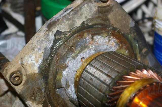
- The motor on mine had clear evidence of at least one of the horrible noises my winch gave out.
- The cable securing bolt on the drum stuck out far enough to foul the motor casing, leaving the sliver wear marks.
- The marks are visible in this picture.
Disassembly
- The motor can be dismantled by undoing the two bolts at the far end of the casing.
- These long bolts reach right through the motor.
Cleaning and re-greasing
- With the casing removed, the motor is exposed.
- There are not a lot of user serviceable parts in the motor.
- However, a good cleanup is worthwhile.
- Water had got in somehow, so there was a lot of rust around.
- I cleaned out the casing and put grease on where the casing mounts to the frame.
- At one end of the motor sits the brushes.
- These are spring mounted, so that they can move as they wear.
- It looks as if they are not replaceable on my motor.
- However, there is an element of maintenance that you can do anyway.
- Check that each brush moves freely in its mount.
- Mine were rusted up and not able to move.
- I gently eased them into moving using WD40 and 3in1.
Re-assembly
- Once the brushes are working, the motor can be re-assembled.
- You have to hold the brushes back, otherwise they foul the commutator as you try and re-assemble it.
The motor case can now be re-assembled.
- Clean the end of the motor housing and again clean and grease the nylon support that the drum sits on.
Final re-assembly of the winch
- Now it's a matter of re-assembling the three components, the drum, the motor and the gear box.
- Insert the brake carefully in the drum along with the hex rod into the gear box.
- Place the cup on the end of the brake and offer up the motor.
- Bolt the winch together and check (with the clutch out) that the drum can be turned.
Mounting the winch back on the vehicle
- Depending on your configuration, you will now have to connect back up the solenoid and offer the entire assembly back up to the car.
- Leave the main bolts holding the winch parts together loose if possible.
- Reason: You really need to check the alignment before tightening everything.
- With the winch loosely mounted in the car and with all the mounting bolts loose and the clutch disengaged, rotate the drum and make sure it rotates smoothly and “straight” within the winch mounts.
- Now tighten all winch bolts and winch mounting bolts up.
Final words
You are done !!! (until the next time)
Page last edited on 21/02/2019 by user Bosanek


