![]() The content of any article might be expanded / improved in the future - revisit it sometimes.
The content of any article might be expanded / improved in the future - revisit it sometimes.
![]() Seen a mistake? Know something that isn't written? Edit and change this article yourself!
Seen a mistake? Know something that isn't written? Edit and change this article yourself!
![]() Some images in the article (if present) can be enlarged by clicking on them.
Some images in the article (if present) can be enlarged by clicking on them.
Contents
Introduction
- The R72 gearbox is fitted to petrol Jimnys from about year 2005.
- The gearbox case splits vertically into three parts - the earlier gearbox splits horizontally.
- Bearing failure seems fairly common on these boxes.
- Many of these were fitted with faulty prop-shafts that allowed oil to leak through the centre cap of the prop, and perhaps oil starvation early in their life contributes to failures.
- All of the deep groove open bearings on the original box are replaced with metal shielded units in Suzuki's parts which implies there may be a general issue in splashing enough oil around.
- DDiS Jimnys use a completely different gearbox (at least the gearbox casing is obviously completely different).
- Therefore, most of this guide is not applicable to DDiS Jimnys.
Rebuild
Tools
- Standard metric sockets and spanners
- Range of impact sockets used to press in bearings
- 2 large flat head screw drivers
- a 2 leg gear puller and/or hydraulic press
- bearing seperator
- torque wrench(s) to cover 23-90Nm
- circlip pliers for 25mm circlips
- copper or plastic mallet
- sturdy metal tube of approx 25mm internal diameter, at least 130mm long; but see text for alternatives
Ideally you'll want a copy of the correct service manual. This gearbox is covered under supplementary service manual 99501-81A20-01E. You might get lucky with Google!
Gearbox Removal
- It is covered elsewhere (need to link).
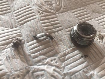
- When draining the gearbox oil, a furry drain plug and chunks of metal are a good sign something has gone wrong in there.
Dismantling
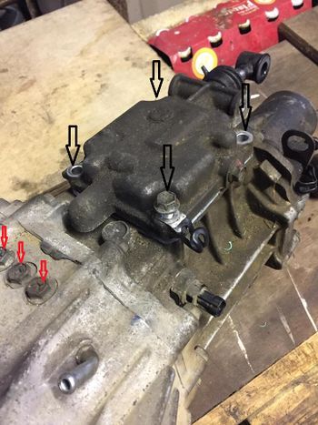
- With the gearbox on your workbench, remove the 4 bolts (black arrows in below picture) holding on the gear change cover and remove.
- It's sealed with liquid gasket and may need a tap with a soft hammer.
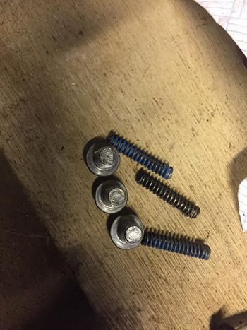
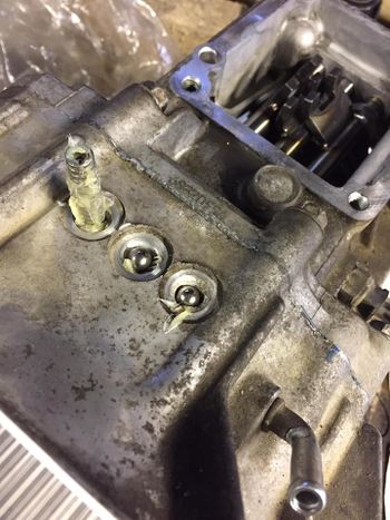
- Remove gear shift locating bolts (red arrows in the picture), springs and ball bearings (not shown).
- There is also a bolt on the opposite side of the case for the reverse gear shaft you need to remove with its spring and bearing.
- The bearings can stick in the shafts.
- If you can't them out at this stage, loosely refit a bolt in the corresponding hole without the spring, so you don't lose the bearing when you start to remove the gear shafts.
Needs something here about rear case removal
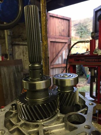
- With the rear case off, you can now see the long output shaft, and the short counter shaft.
- This picture was taken on reassembly with a new sealed bearing on the counter shaft.
- From the factory this was an open bearing on my 2009 model.
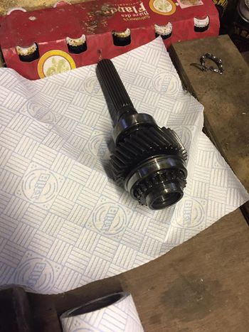
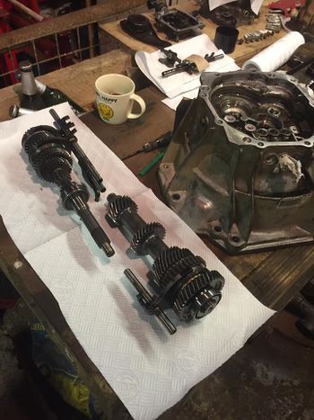
- The output shaft lifts away easily.
- Do this slowly and make sure nothing lose is stuck to the bottom of this ready to fall on the floor.
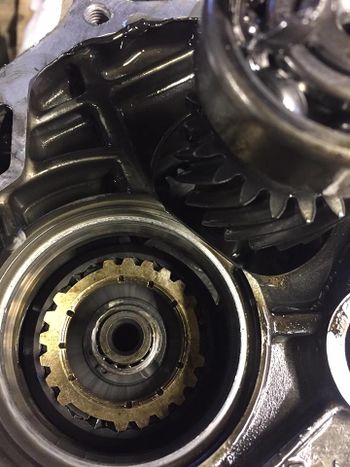
- Looking down on to what is the input shaft, you should be left with the a synchroniser ring (brass colour).
- Under this is a round, lose clip, and in the centre a needle roller bearing.
- It's worth lifting these out now and keeping safely, in the correct order with your output shaft.
- They'll only fall out and disappear later when you pull out the input shaft.
Something about removing the mid case here.
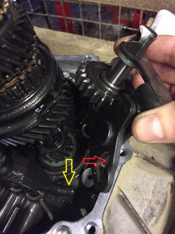
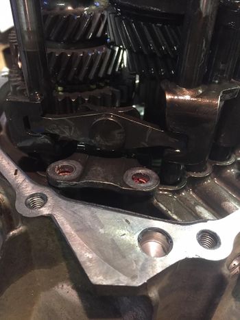
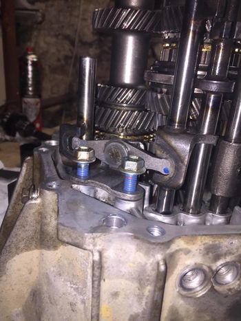
- Remove the reverse gear.
- Be careful here, the lever plate (red arrow), connects to one of the shift rods (yellow arrow).
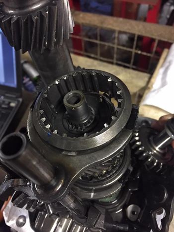
- If you lift the shift rod it will probably pop off a synchro sleeve on the input shaft, and synchro keys will fall on the floor, and you will be sad.
- This is a sad synchro sleeve with synchro keys no where to be seen.
- Don't let the sleeve lift as much as this. You have been warned!
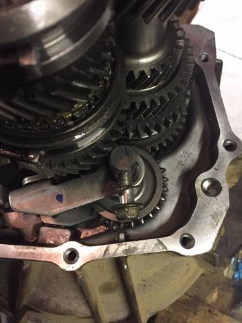
- Next remove the 5th gear shift inverse lever at the base of the shift rods.
- Just two bolts and lift it out.
- At this stage you can release the large circlip at the base of the input shaft and lift away both the input and counter shafts plus the shift rods.
Bearing Replacement
I jumped the gun a bit and got going before dismantling everything.
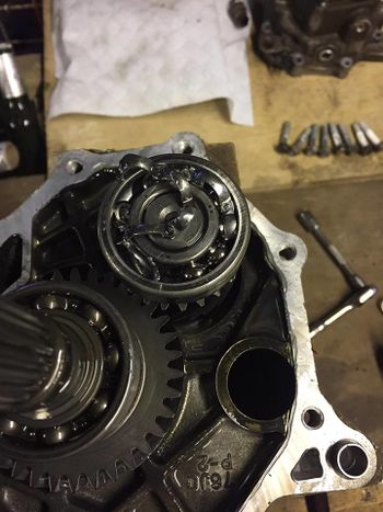
- This is the top of the counter shaft.
- Fairly obvious what is wrong here.
- In fact this is the only bearing that appeared sub-optimal in my box.
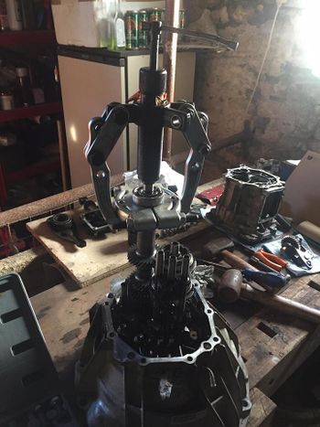
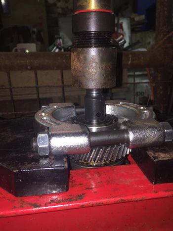
- So I removed it with a hydraulic puller and bearing splitter.
- None of the bearings took much effort to remove.
- I'd be confident this could be done with a manual puller.
- Bearing removal is trickier when the bearing is at the bottom of a shaft.
- You could possibly have tapped this off from behind.
- On the output shaft there are bearings either side of the gear and the whole lot needs pulling off.
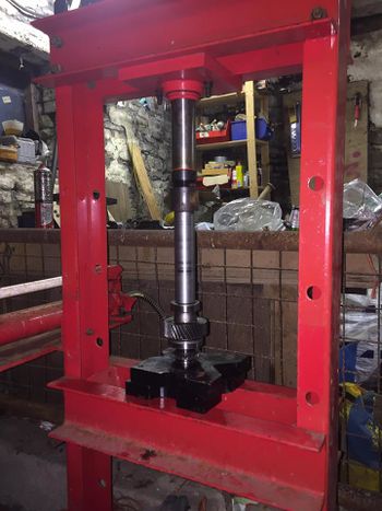
- I did them one component at a time using a bearing splitter and a hydraulic press.
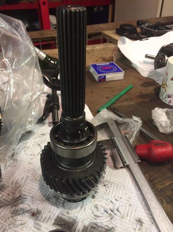
- This isn't the output shaft, but you get the idea.
- A better idea of what you are up against with the output shaft here.
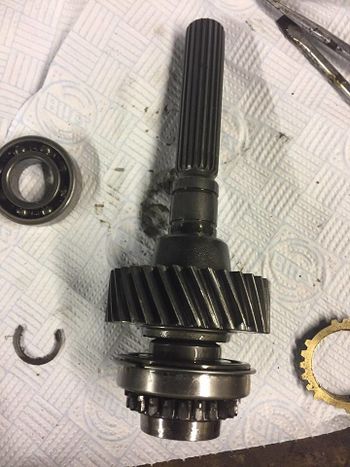
- None of this was hard to pull off.
- Remember - it's the bearing shown removed, plus the gear, plus the bearing below the gear with integral circlip (with the splitter and press).
- Note the blind circlip.
- There's a couple of these about but actually they weren't much of a problem.
- Lean on either side with 2 big flathead screwdrivers and they ping off.
- Sometimes they even remain in sight.
- The problem comes when you want to push bearings back onto the shaft.
- Bearings at the top of shafts are easy if you have a range of impact sockets to act as suitable size presses.
- But my sockets aren't deep enough for output shafts.
- You could tap the bearings on with a brass rod and a hammer.
- If you do this it will be very easy to slip off the center race.
- Put the old bearing on top of the new one and drive on that to protect it.
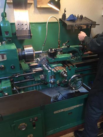
- Luckily I know a man with a lathe who drilled a 25mm hole in some 40mm bar.
- I don't know what a machine shop would charge to do this but it made driving the bearings back on very easy.
- Both bearings and the gear drive on in one action with a press.
Oil Seal Replacement
Next job is the oil seals.
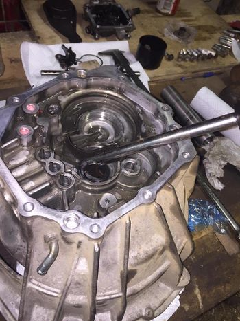
- One of these oil seal removal tools will do the job.
- Be *very* careful not to score the casting with one of these.
- Err on the side of caution.
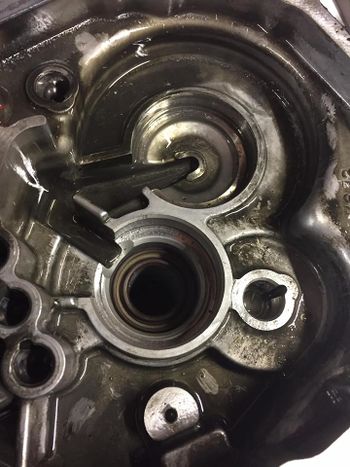
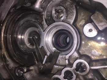
- There are two oil seals to remove where the input shaft passes through the bell housing.
- Tap new seals into place using a suitable sized drift.
- Impact sockets are good for this.
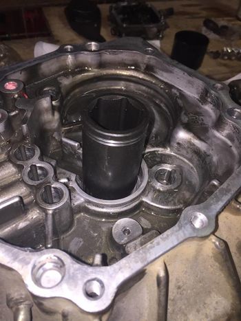
- The first seal needs to go in with the solid face down.
- Ideally you will have a solid disk to press it in with, because you only have the open (U cross-section) of the seal to press on.
- I was lucky, a 30mm impact socket used upside down did the trick (see the picture).
- The seal lip of this seal should have grease on it. The genuine Suzuki seals come ready greased.
- Here is the first seal in place.
- And the second seal.
There is also the output shaft seal to replace in the same way in the rear case.
Reassembly
Is the reverse of disassembly, obviously. Nothing tricky here. A few points to note.
- The fifth gear shift inverse lever needs threadlock on its bolts.
- Torque to 23Nm.
- The gear shift locating springs and ball bearings are greased and replaced.
- The bolts need threadlock (wipe any grease off the case threads), and are torqued to 13Nm (every other bolt on the gearbox is 23Nm).
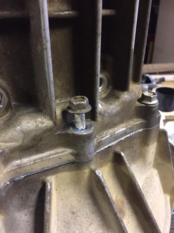
- The reverse gear shaft needs to be positioned such that the bolt that secures it from outside of the centre case will thread into it.
- There is a small ridge in the casting to line up, but trial fit the centre case and make sure this is exactly right.
- Before the final fit of the centre case to the bell housing, apply instant gasket sealant.
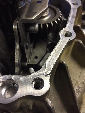
- The picture below shows what a bit too much sealant looks like.
- Quite a lot oozed out when I tightened it, meaning a fair bit must have oozed in too.
- The gearbox cases bolt together.
- No threadlock required.
- Guess what? 23Nm.
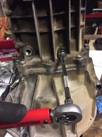
- And here is the bolt being tightened up to 23Nm in the reverse gear shaft which you aligned carefully.
All that remains is to fit the rear case. Use sealant on the mating surfaces. Torque bolts to 23Nm.
And the gear shift plate. Sealant on mating surfaces, and thread lock on the bolts. Torque to 23Nm.
Now simply (!) refit the gearbox and away you go.
Torque Settings
Full details of the torque settings can be found in the reference data
Page last edited on 13/07/2017 by user Bosanek

