Difference between revisions of "Manual or fixed front wheel hub heads"
(Massive expansion and revamping of the entire article, to fully encompass the topic of changing over to manual hub heads!) |
(Link correction) |
||
| (49 intermediate revisions by 2 users not shown) | |||
| Line 5: | Line 5: | ||
| − | + | [[File:Vacuum operated wheel hub head on a wheel - B01.jpg|thumb|384px|left|Vacuum operated free-wheeling wheel hub head on a wheel]] | |
| + | * Jimnys have pneumatically (vacuum) operated free-wheeling front wheel hub heads / caps. | ||
| + | * Pneumatic system is very convenient when it works, but it can be a nightmare when it fails. | ||
| − | |||
| + | * Most Jimnys (especially those which are regularly used in all-terrain duty) will, inevitably, have problems with the vacuum system for front wheel hub heads. | ||
| + | * Diagnosis and repair, depending on the issue, can range from a quick detection and a simple/cheap fix, to a thorough and arduous investigation with expensive repairs. | ||
| + | <br clear="all"> | ||
| − | |||
| − | |||
| − | |||
| − | |||
| − | |||
| − | |||
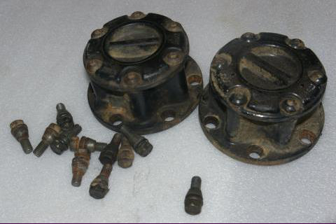
| + | [[File:Vacuum and manual wheel hub head - A01.jpg|thumb|left|400px|Vacuum (top) and manual (bottom) free wheeling wheel hub head for a comparison]] | ||
| + | * There is luckily an alternative remedy - to eliminate the entire vacuum system and with it all the risks and issues which it imposes. | ||
| + | * The required modifications are relatively simple to perform, with required parts widely available on the second hand market and/or in the aftermarket. | ||
| + | <br clear="all"> | ||
| − | |||
| + | Elimination of the vacuum system is worth considering in the following scenarios: | ||
| + | # If you are tired with chasing faults in your vacuum system for front wheel hub heads; | ||
| + | # If the determined repair of the fault is too expensive; | ||
| + | # If you just want to preventively minimize the risk of a failure (which usually occurs when it is most inconvenient); | ||
| − | |||
| + | The purpose of this article is to fully explain all the '''three''' possible solutions to eliminate the vacuum system: | ||
| + | # Replacing it altogether with manually operated free-wheeling front wheel hub heads; | ||
| + | #* Like in Samurais and other classic 4WD vehicles; | ||
| + | # Replacing it altogether with fixed front wheel hub heads; | ||
| + | # Converting original vacuum operated free-wheeling front wheel hub heads into fixed hub heads; | ||
| − | |||
| + | All three solutions share many common steps. | ||
| − | |||
| − | |||
| − | |||
| + | To clear any misconceptions: | ||
| + | * Free wheeling (and fixed) wheel hub heads of any type have no relation to differential lockers or with the action of locking a differential. | ||
| + | * They also have no relation to reduction gearing, nor with any form of traction control. | ||
| + | * And they generally don't bring bad nor good luck! | ||
| + | * On the other hand, if you paint them to look sexy, they might attract some females (depending on the species - wolf, bear, snake, skunk, etc.). | ||
| + | <br clear="all"> | ||
| − | + | {{note|This article certainly appears gargantuan and overwhelming.<br>It is large because it contains all the solutions for all the situations.<br><br>Only some of those will be applicable to your case and desires.<br>Therefore, only certain parts of this article will actually interest you.}} | |
| − | + | {{note|Before hastily embarking on any of the three solutions mentioned above, you might first consider repairing your original vacuum system.<br><br>The wiki article [[4WD transmission failure diagnostics|'''"4WD transmission failure diagnostics"''']] contains detailed information on how to diagnose and repair the vacuum system.}} | |
| − | |||
| − | |||
| − | |||
| − | |||
| − | |||
| − | |||
| + | {{note|In order to properly understand this article, you should first properly understand the operating principles of Jimny's entire 4WD transmission system.<br> That topic is covered in a dedicated wiki article [[4WD transmission system operation|'''"4WD transmission system operation"''']].}} | ||
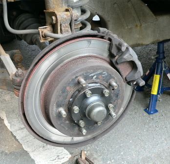
| − | + | {{note|Wheel hub heads / caps are usually just shortened in naming to "hubs", but a "hub" is actually an entire wheel hub assembly - the casing which contains the wheel bearing with its seals, the steering knuckle surround casing, the king pin bearings and (in the case of the Jimny) the pipes and passages which transport the air / vacuum through the wheel hub assembly to/from wheel hub heads.}} | |
| − | == | + | == Quick overview of the solutions == |
| − | |||
| − | |||
| + | === Solution with manually operated hub heads === | ||
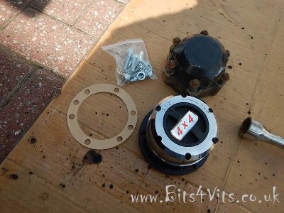
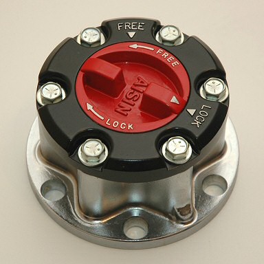
| − | + | [[File:Manually operated wheel hub head - A01.jpg|thumb|384px|left|Manually operated free-wheeling wheel hub head]] | |
| + | <br clear="all"> | ||
| + | ==== Advantages ==== | ||
| − | |||
| + | * Still allows the front drive line to be (dis)engaged at operator's will in order to save on fuel and mechanical wear of the drive line when using the vehicle in 2WD transmission mode. | ||
| + | * Generally robust and simple mechanical (dis)engagement system with the least amount of components which can fail compared to automatic and vacuum operated systems. | ||
| + | ** In very rare cases when it fails, the cause is easy to detect and fix. | ||
| + | * Manually operated front wheel hub heads indirectly allow the use of the "'''2WD-L'''" transmission mode. | ||
| + | ** Suzuki has not enabled that mode by default in any Jimny. | ||
| + | ** Read the wiki article [[2WD-L transmission mode|'''"2WD-L transmission mode"''']] for all the details. | ||
| − | + | ||
| − | + | ==== Disadvantages ==== | |
| − | |||
| − | |||
| − | This | + | * The operator has to exit the vehicle and manually switch both hub heads whenever their (dis)engagement is desired. |
| − | + | * As most manual free wheeling hub heads have no anti-tamper mechanisms, a malicious person can easily (dis)engage a hub head while the vehicle is parked. | |
| − | + | ** This is easily remedied by the driver when detected, but can cause confusion while driving in the meantime. | |
| − | + | * If water enters into a manual free wheeling hub head, it can freeze the manual (un)locking spring mechanism in the hub head during frigid weather. | |
| + | ** If this happens while the hub head is disengaged, it can prevent the vehicle from using 4WD transmission when it is needed the most. | ||
| − | + | ==== Practical tips when using manual wheel hub heads ==== | |
| − | |||
| − | |||
| − | |||
| − | |||
* It is NOT strictly required to engage/disengage the wheel hub heads every time when switching between <font face="courier">2WD<->4WD</font> transmission modes. | * It is NOT strictly required to engage/disengage the wheel hub heads every time when switching between <font face="courier">2WD<->4WD</font> transmission modes. | ||
* In other words, it is completely fine to leave the wheel hub heads engaged during 2WD transmission mode. The vehicle will just use a bit more fuel (since more metal is spinning) and that metal will naturally wear more compared to when being disconnected and resting idle. | * In other words, it is completely fine to leave the wheel hub heads engaged during 2WD transmission mode. The vehicle will just use a bit more fuel (since more metal is spinning) and that metal will naturally wear more compared to when being disconnected and resting idle. | ||
* This means that you can have the hub heads engaged all the time during the day(s) when you expect to shift between <font face="courier">2WD<->4WD</font> transmission modes often. This will save you many exists from the vehicle. | * This means that you can have the hub heads engaged all the time during the day(s) when you expect to shift between <font face="courier">2WD<->4WD</font> transmission modes often. This will save you many exists from the vehicle. | ||
| + | |||
| + | |||
* If you suspect upcoming freezing weather conditions (for example for the next morning after parking the car in the evening), it might be a good precautionary measure to leave the hub heads engaged over night on the parking lot, in case that the (un)locking mechanism in them freezes. Better to have them frozen ON than frozen OFF! | * If you suspect upcoming freezing weather conditions (for example for the next morning after parking the car in the evening), it might be a good precautionary measure to leave the hub heads engaged over night on the parking lot, in case that the (un)locking mechanism in them freezes. Better to have them frozen ON than frozen OFF! | ||
| + | |||
| + | |||
* Develop a habit to occasionally check the (dis)engagement status of your manual hub heads, in case that someone has fiddled with them on a parking lot! | * Develop a habit to occasionally check the (dis)engagement status of your manual hub heads, in case that someone has fiddled with them on a parking lot! | ||
| + | |||
| + | |||
| + | === Solution with fixed wheel hub heads === | ||
| + | |||
| + | |||
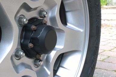
| + | [[File:Fixed wheel hub head on a wheel - A01.jpg|thumb|left|348px|Fixed wheel hub head on a wheel]] | ||
| + | |||
| + | * It is also possible to install fixed wheel hub heads. | ||
| + | * The procedure for performing the conversion to fixed hub heads is exactly the same as the procedure for the conversion to manually operated wheel hub heads. | ||
| + | * Therefore, this article can be fully utilized for that type of conversion as well. | ||
| + | <br clear="all"> | ||
| + | |||
| + | |||
| + | ==== Advantages ==== | ||
| + | |||
| + | |||
| + | The advantages of fixed hub heads vs. manual hub heads: | ||
| + | * Nobody can maliciously disengage them on a parking lot; | ||
| + | * They are usually the most durable type for extremely heavy-duty operation; | ||
| + | * Fixed hub heads are usually much smaller than any other type of hub head. | ||
| + | ** Their much smaller size means that they protrude much less from the wheel to the sides, minimizing chances of hitting something and getting damaged in extremely heavy-duty all-terrain use. | ||
| + | |||
| + | |||
| + | ==== Disadvantages ==== | ||
| + | |||
| + | |||
| + | * Their availability on the aftermarket for Jimnys is much lower. | ||
| + | * Possible sources would be from a SJ413 (Samurai) and from Vitara Mk1 (and possibly from Vitara Mk2 as well?), but it is not known if some additional spacers are required. | ||
| + | * The only operational disadvantage compared to manually operated free-wheeling wheel hub heads is that you will never be able to disengage the front wheels from the drive line. | ||
| + | ** Nothing will break, but the vehicle will use slightly more fuel in 2WD transmission mode and the front drive line will naturally wear slightly more, since it will be always working as opposed to working only when the transmission is in 4WD mode. | ||
| + | ** This is the same operational effect as when having manually operated wheel hub heads engaged all the time. | ||
| + | * [[2WD-L transmission mode|'''"2WD-L transmission mode"''']] can not be used. | ||
| + | |||
| + | |||
| + | === Solution with converting original vacuum wheel hub heads into fixed hub heads === | ||
| + | |||
| + | |||
| + | * Jimny's original vacuum-operated front wheel hub heads can be relatively easily modified so that they become fixed (always engaged). | ||
| + | * The modifications can be accomplished in a few ways. | ||
| + | ** Some are reversible and some are irreversible. | ||
| + | * The procedure is described in detail further down in this article. | ||
| + | |||
| + | |||
| + | ==== Advantages ==== | ||
| + | |||
| + | |||
| + | * No new (replacement) fixed hub heads are needed. | ||
| + | ** Therefore zero costs of the conversion! | ||
| + | * After the vacuum hub heads are converted to fixed hub heads, the part 2 (and possibly part 3 as well, depending on your choices below) of the conversion process in the next chapter still need(s) to be performed. | ||
| + | |||
| + | |||
| + | ==== Disadvantages ==== | ||
| + | |||
| + | |||
| + | * Front drive line remains always engaged and can not be disengaged any more. | ||
| + | ** Nothing will break, but the vehicle will use slightly more fuel in 2WD transmission mode and the front drive line will naturally wear slightly more, since it will be always working as opposed to working only when the transmission is in 4WD mode. | ||
| + | * This is the same operational effect as when having manually operated wheel hub heads engaged all the time. | ||
| + | * Vacuum operated wheel hub heads are generally the least durable for heavy all-terrain duty compared to other hub head types, especially when they are DIY modified. | ||
| + | * [[2WD-L transmission mode|'''"2WD-L transmission mode"''']] can not be used. | ||
| Line 91: | Line 162: | ||
=== Introduction === | === Introduction === | ||
| + | |||
| + | Although this article appears enormous in length, don't be overwhelmed - it is really rather simple, but it has been "broken down" to each phase and option and written in detail - hence the length. | ||
| + | |||
| + | |||
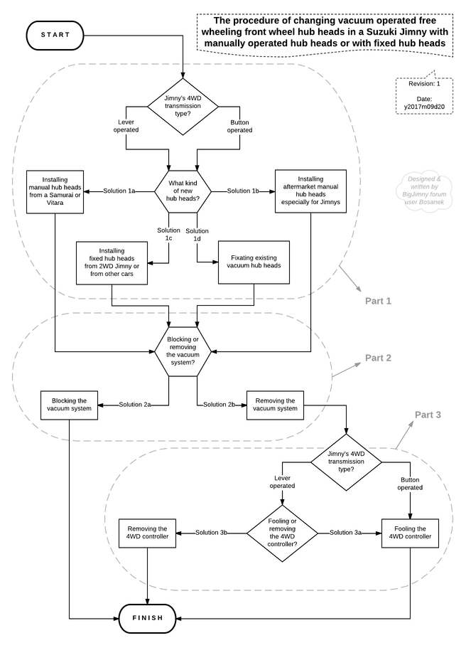
| + | [[File:Manual or fixed front wheel hubs on a Jimny - modification diagram - A01.png|thumb|left|656px|The entire modification procedure in a neat overview diagram]] | ||
This modification is performed in three parts: | This modification is performed in three parts: | ||
| − | # Removing the old vacuum operated hub heads and installing manually operated hub heads; | + | # Removing the old vacuum operated hub heads and installing manually operated hub heads (or fixed hub heads); |
# Blocking or removing the vacuum system (valves, pipes); | # Blocking or removing the vacuum system (valves, pipes); | ||
# Fooling the 4WD controller into thinking that the vacuum system still works as normal, or removing the 4WD controller altogether. | # Fooling the 4WD controller into thinking that the vacuum system still works as normal, or removing the 4WD controller altogether. | ||
| − | * | + | * All three parts of the modification are rather simple to perform. |
| − | * The | + | * The first two parts are quite "straightforward". |
| − | * The | + | * The choices in the third part differ for vehicles with manually operated transfer boxes and for vehicles with electrically operated transfer boxes. |
| + | * Reason: While the 4WD controller can be completely discarded in the older (lever-operated) transmission system, it has to remain fully working in the newer (button-operated) transmission system. | ||
| + | |||
| + | |||
| + | {{note|The wiki article [[4WD transmission system operation|'''"4WD transmission system operation"''']] explains in detail how Jimny's 4WD transmission system operates.<br>It is vital in understanding why some steps in this procedure are performed.}} | ||
| + | <br clear=all> | ||
| + | |||
| + | |||
| + | === Part 1: Installing fixed or manually operated hub heads === | ||
| − | === | + | ==== Introduction ==== |
* This phase of the conversion is the same for all Jimnys. | * This phase of the conversion is the same for all Jimnys. | ||
| − | * There are | + | * There are four solutions on how to achieve it. |
| + | |||
| + | |||
| + | ==== Solution 1a - old manual hub heads from a Samurai or a Vitara ==== | ||
| + | |||
| + | |||
| + | ===== Introduction ===== | ||
| + | |||
| + | |||
| + | * This solution is less expensive of the two solutions with manually operated free wheeling hub heads, but involves more "fiddling" around. | ||
| + | * The additional required "fiddling" is because the hub heads from earlier Suzuki vehicles do not fit/mate directly on Jimny's wheel hubs. | ||
| + | ** The cause for that is the presence of a special metallic vacuum sealing ring in Jimny's wheel hub assembly. | ||
| + | |||
| + | |||
| + | ===== Resolving incompatibility ===== | ||
| + | |||
| + | |||
| + | This incompatibility can resolved by either of the following two methods: | ||
| + | # By installing a pair of special spacers/adapters (with suitable bolts), which sit between the newly obtained hub heads and the wheel hub assembly. | ||
| + | # By undoing the locking hub nut and grinding off the vacuum sealing ring. | ||
| + | |||
| + | |||
| + | Advantages and disadvantages of method 1: | ||
| + | * '''А''': Potentially cheaper, simpler to perform and entirely reversible (possible to return the wheel hub assembly back to the original setup); | ||
| + | * '''D''': Reduces the length of the spline contact between the wheel hub head and the short drive shaft part of the CV joint. | ||
| + | ** Therefore, method 1 weakens that point in the drive line, making this method less suitable for heavy-duty off road use. | ||
| + | *** (In other words: increased risk of damage to the wheel hub head or to the CV joint). | ||
| + | |||
| + | |||
| + | Advantages and disadvantages of method 2: | ||
| + | * '''A''': Does '''not''' reduce the spline contact surface between the wheel hub head and the short drive shaft part of the CV joint. | ||
| + | ** Therefore, the strength of this point in the drive line is preserved. | ||
| + | * '''A/D''': Requires the purchase and use of a special tool to undo the hub nut. | ||
| + | ** That tool is usually more expensive than the pair of spacers from method 1. | ||
| + | ** However, that tool is also required when changing a front wheel bearing on a Jimny. | ||
| + | *** Therefore, the purchase of this tool might be a good investment anyway for the future. | ||
| + | * '''D''': More complicated to perform (grinding work). | ||
| + | * '''D''': The wheel hub assembly will be irreversibly altered, preventing any future use of Jimny's air locking wheel hub heads (if you ever happen to wish to return to them). | ||
| + | |||
| + | |||
| + | ===== Required parts ===== | ||
| + | |||
| + | |||
| + | {{note|There are numerous versions and editions of Suzuki SJ 413s, Samurais and Vitaras / Escudos / Sidekicks / Geotrackers in existence.<br>Only some of them had manual hub heads as a factory fitment, and Suzuki used hub heads from several OEMs.<br>With any second-hand equipment, checking its condition beforehand is always vital!}} | ||
| + | |||
| + | |||
| + | [[File:Manual wheel hub head from Suzuki SJ 41x installation guide - figure 01.png|thumb|left|480px|Figure 01 - SJ manual hub heads]] | ||
| + | |||
| + | * A pair of manually operated, second hand hub heads from any Suzuki SJ 413 (Samurai) or from any Suzuki Vitara (Escudo / Sidekick / GeoTracker) Mk1. | ||
| + | <br clear="all"> | ||
| + | |||
| + | [[File:Manual wheel hub head from Suzuki SJ 41x installation guide - figure 02.png|thumb|left|480px|Figure 02 - The cone washers from SJ hub head bolts]] | ||
| + | * The cones from the SJ / Vitara hub head bolts. | ||
| + | <br clear="all"> | ||
| + | |||
| + | |||
| + | Also required for performing incompatibility remedy method 1: | ||
| + | |||
| + | [[File:Manual wheel hub head from Suzuki SJ 41x installation guide - figure 03.png|thumb|left|480px|Figure 03a - wheel hub head spacer rings]] | ||
| + | |||
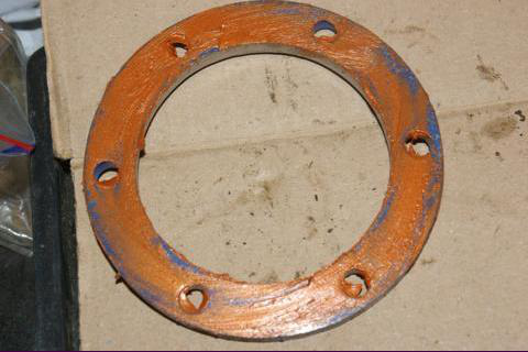
| + | * A pair of special wheel hub head spacer rings; | ||
| + | |||
| + | |||
| + | * Browse the shops like BigJimny, JimnyBits, Bits4Vits, etc. for suitable spacers/adapters (method 1) or for the special tool (method 2). | ||
| + | * If you decide for method 1, BigJimny sells a suitable kit. | ||
| + | ** In the kit you get two spacer rings and 12 Hex cap bolts. | ||
| + | ** The kit includes replacement bolts as the Jimny and SJ bolts are too long and too short respectively. | ||
| + | |||
| + | |||
| + | * This picture shows the BigJimny rings (the photo is of the prototype rings painted blue, the shop versions are properly plated): | ||
| + | <br clear="all"> | ||
| + | |||
| + | |||
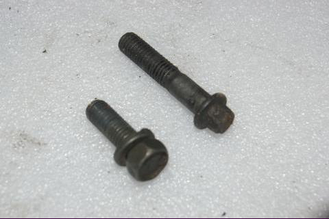
| + | [[File:Manual wheel hub head from Suzuki SJ 41x installation guide - figure 04.png|thumb|left|480px|Figure 04 - SJ and Jimny bolts]] | ||
| + | |||
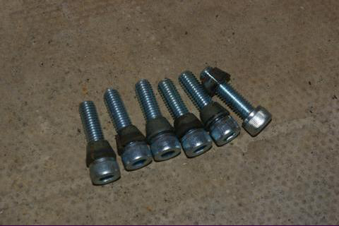
| + | * A set of bolts for securing the wheel hub head to the wheel hub assembly. | ||
| + | * Suitable bolts should be supplied together with the wheel hub head spacer rings. | ||
| + | <br clear="all"> | ||
| + | |||
| + | |||
| + | Also required for performing incompatibility remedy method 2: | ||
| + | |||
| + | [[File:Hub nut tool.jpg|thumb|left|375px|Figure 03b - special "hub nut unlock tool"]] | ||
| + | |||
| + | * The special tool to undo the wheel hub assembly locking nut. | ||
| + | |||
| + | |||
| + | * Some kind of a grinding tool is also required. | ||
| + | <br clear="all"> | ||
| + | |||
| + | |||
| + | ===== Installation guide ===== | ||
| + | |||
| + | |||
| + | The replacement procedure is really simple and straightforward. | ||
| + | |||
| + | {{note|This guide shows the procedure with incompatibility remedy method '''1''' applied.}} | ||
| + | |||
| + | |||
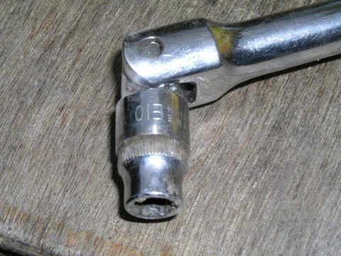
| + | [[File:Manual wheel hub head from Suzuki SJ 41x installation guide - figure 05.png|thumb|left|480px|Figure 05 - E10 "Torx" socket]] | ||
| + | |||
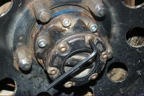
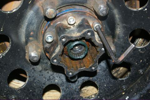
| + | * First remove both Jimny vacuum hub heads using an E10 Torx socket. | ||
| + | <br clear="all"> | ||
| + | |||
| + | |||
| + | [[File:Manual wheel hub head from Suzuki SJ 41x installation guide - figure 06.png|thumb|left|480px|Figure 06 - spacer ring coated with sealant]] | ||
| + | |||
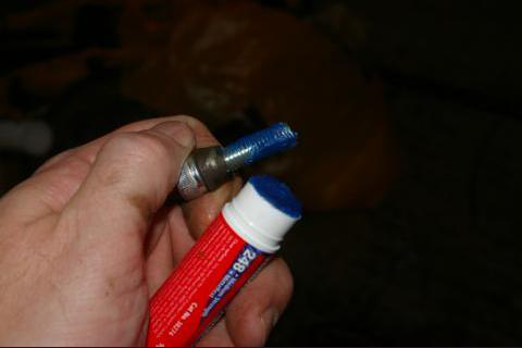
| + | * Coat the spacer ring with a thin layer of sealant to keep the water out. | ||
| + | <br clear="all"> | ||
| + | |||
| + | |||
| + | |||
| + | [[File:Manual wheel hub head from Suzuki SJ 41x installation guide - figure 07.png|thumb|left|480px|Figure 07 - SJ cone washers on the new bolts]] | ||
| + | |||
| + | * Slide the cones from the SJ hubs onto the new bolts. | ||
| + | <br clear="all"> | ||
| + | |||
| + | |||
| + | [[File:Manual wheel hub head from Suzuki SJ 41x installation guide - figure 08.png|thumb|left|480px|Figure 08 - Coated bolt with thread locker]] | ||
| + | |||
| + | * Now coat the bolts with a thin layer of thread locker. | ||
| + | <br clear="all"> | ||
| + | |||
| + | |||
| + | [[File:Manual wheel hub head from Suzuki SJ 41x installation guide - figure 09.png|thumb|left|480px|Figure 09 - removing the SJ hub heads's front plate]] | ||
| + | |||
| + | * Mate the hub head to the wheel hub and screw the bolts in by finger as far as possible. | ||
| + | * You may find that the front of the hub head prevents you from getting at the new bolts. | ||
| + | * In this case, set the hub head to FREE position and undo the hub head's front plate. | ||
| + | <br clear="all"> | ||
| + | |||
| + | |||
| + | [[File:Manual wheel hub head from Suzuki SJ 41x installation guide - figure 10.png|thumb|left|480px|Figure 10 - tightening the bolts]] | ||
| + | |||
| + | * Now you should be able to tighten the bolts. | ||
| + | * Tighten them sequentially in a "star" pattern, like when mounting a wheel. | ||
| + | * Go around the hub a couple of times to tighten the bolts fully. | ||
| + | <br clear="all"> | ||
| + | |||
| + | |||
| + | [[File:Manual wheel hub head from Suzuki SJ 41x installation guide - figure 11.png|thumb|left|480px|Figure 11 - successfully installed manual SJ 413 hub head]] | ||
| + | |||
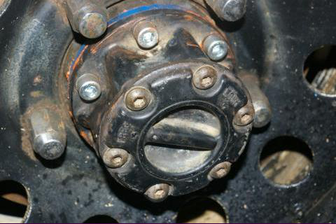
| + | * Now refit the SJ hub head front plate and admire the finished installation. | ||
| + | <br clear="all"> | ||
| + | |||
| + | |||
| + | ==== Solution 1b - aftermarket tailor-made Jimny manual hub heads ==== | ||
| + | |||
| + | |||
| + | This solution is usually more expensive one of the two solutions with manually operated free wheeling hub heads, but is much more elegant. | ||
| + | |||
| + | |||
| + | Its elegance consists of the following: | ||
| + | * No special tools, spacers, rings, bolts, potions, magic wands, etc. are required. | ||
| + | * Compared to solution 1a with method 1, it does '''not''' reduce the spline contact surface between the wheel hub head and the short drive shaft part of the CV joint. | ||
| + | ** Therefore, the strength of this point in the drive line is preserved. | ||
| + | * Compared to solution 1a with method 2, the entire installation is completely reversible (it is easily possible to return the wheel hub assembly back to the original setup). | ||
| + | |||
| + | In other words, with solution 1a you have to either weaken the drive line strength or to irreversibly alter the wheel hub assembly, but with solution 1b, no such compromises need to be made. | ||
| − | + | Also, if you manage to find these hub heads second-hand but in good condition, this solution might quite well even be cheaper than solution 1a! | |
| − | |||
| − | |||
| − | |||
| − | |||
| − | Required parts | + | Required parts: |
* A pair of aftermarket-made manually operated hub heads which are specifically designed for Jimnys. | * A pair of aftermarket-made manually operated hub heads which are specifically designed for Jimnys. | ||
| − | * These are a direct "bolt-on" replacement - no | + | ** These are a direct "bolt-on" replacement (just use original existing bolts)! |
| + | |||
| + | |||
| + | Examples of aftermarket brands of tailor-made manual hub heads for Jimnys: | ||
| + | * AVM, hub head model 457 | ||
| + | ** These allegedly exist in two editions - blue (cheaper/weaker) and red (expensive/stronger) | ||
| + | * Tyre X | ||
| + | * Various no name | ||
| + | * Others? | ||
| + | |||
| + | |||
| + | The described installation procedure from solution 1a can be generally applied here as well, except that it is much simpler in this case. | ||
| + | |||
{{note|The quality of aftermarket manual hub heads for Jimnys varies depending on a brand. There are even some no-name models around. You get what you pay for!}} | {{note|The quality of aftermarket manual hub heads for Jimnys varies depending on a brand. There are even some no-name models around. You get what you pay for!}} | ||
| − | Required tools: | + | |
| + | ==== Solution 1c - fixed hub heads ==== | ||
| + | |||
| + | |||
| + | This solution should be the most robust, but the parts might be hard to find. | ||
| + | |||
| + | |||
| + | Required parts: | ||
| + | * A pair of compatible fixed hubs for Jimnys. | ||
| + | * Depending on their source, you might need some spacers/adapters for them. | ||
| + | |||
| + | {{note|This solution needs additional info from someone who has done this.}} | ||
| + | |||
| + | |||
| + | ==== Solution 1d - converting existing vacuum hub heads into fixed hub heads ==== | ||
| + | |||
| + | |||
| + | ===== Introduction ===== | ||
| + | |||
| + | |||
| + | * There are no additional parts required for this solution. | ||
| + | * Therefore, it is the cheapest of all solutions - zero costs! | ||
| + | * It just needs some ingenuity and some mechanical (or optionally welding) skills in order to fixate the hub heads. | ||
| + | * The best of all - this modification is entirely reversible (unless you get angry and weld something). | ||
| + | * The goal of this solution is to simply forcibly jam the internal (un)locking mechanism of the original vacuum hub head into the "locked" position. | ||
| + | ** This gives the same effect as having a fixed wheel hub head, or as having a manually locking wheel hub head locked all the time. | ||
| + | |||
| + | |||
| + | {{note|Beware that, in general case, the strength / robustness of modified (fixated) vacuum hub heads can never match the strength of true fixed hub heads, no matter which method to modify (fixate) them was utilized.}} | ||
| + | |||
| + | |||
| + | ===== Conversion guide ===== | ||
| + | |||
| + | |||
| + | [[File:Vacuum hub head to fixed hub head conversion guide - figure 01.jpg|thumb|left|500px|Figure 01 - demounted original vacuum wheel hub head]] | ||
| + | |||
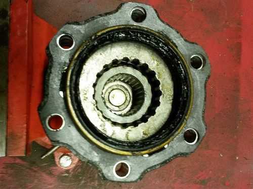
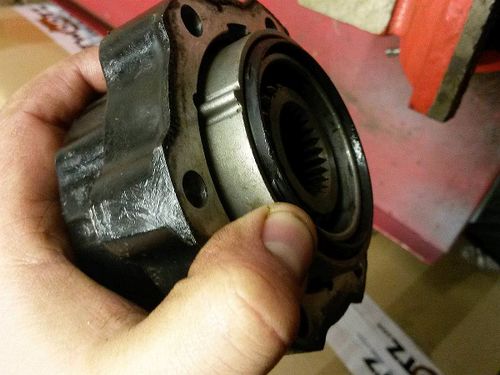
| + | * Here is an original Suzuki vacuum wheel hub head when demounted from a Jimny. | ||
| + | <br clear="all"> | ||
| + | |||
| + | |||
| + | [[File:Vacuum hub head to fixed hub head conversion guide - figure 02.jpg|thumb|left|500px|Figure 02 - removing the vacuum seal from the hub head]] | ||
| + | |||
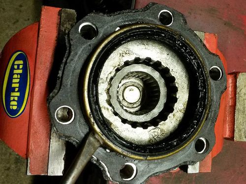
| + | * There is a vacuum seal in the hub head that needs levering off. | ||
| + | * It will not be strictly needed after the "fixation" of the hub head is complete. | ||
| + | * Therefore, it can be re-used by someone else to repair their genuine Jimny vacuum hub head (if your seal is good and their seal is faulty). | ||
| + | * In that case, their faulty seal would serve just fine in your fixated hub head, because it will just serve to generally keep most of water and grit out. | ||
| + | <br clear="all"> | ||
| + | |||
| + | |||
| + | [[File:Vacuum hub head to fixed hub head conversion guide - figure 03.jpg|thumb|left|500px|Figure 03 - pulling out the gearing]] | ||
| + | |||
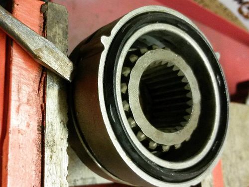
| + | * Then pull out this gearing ... | ||
| + | <br clear="all"> | ||
| + | |||
| + | |||
| + | [[File:Vacuum hub head to fixed hub head conversion guide - figure 04.jpg|thumb|left|500px|Figure 04 - throwing out the center bits]] | ||
| + | |||
| + | * Turn the hub head upside down and the center bits should come out. | ||
| + | * It might need a sharp tap on the bench. | ||
| + | <br clear="all"> | ||
| + | |||
| + | |||
| + | [[File:Vacuum hub head to fixed hub head conversion guide - figure 05.jpg|thumb|left|500px|Figure 05 - splitting the castings]] | ||
| + | |||
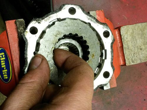
| + | * The center is made of two alloy castings. | ||
| + | * The two castings are pressed together with the hollow inner splined shaft within them, that pushes in and out. | ||
| + | * It is this hollow splined shaft that, when pushed out, slides into the geared ring, which in turn sits inside the geared part of the casing, that bolts to the hub of the car. | ||
| + | * The splined end of the CV joint slides inside the hollow splined shaft. | ||
| + | * When all is linked like this, the drive force can be transmitted from the transmission to the wheel. | ||
| + | |||
| + | |||
| + | * Carefully split the two castings from each other, as shown in the picture. | ||
| + | <br clear="all"> | ||
| + | |||
| + | |||
| + | [[File:Vacuum hub head to fixed hub head conversion guide - figure 06.jpg|thumb|left|500px|Figure 06 - a surprise spring inside]] | ||
| + | |||
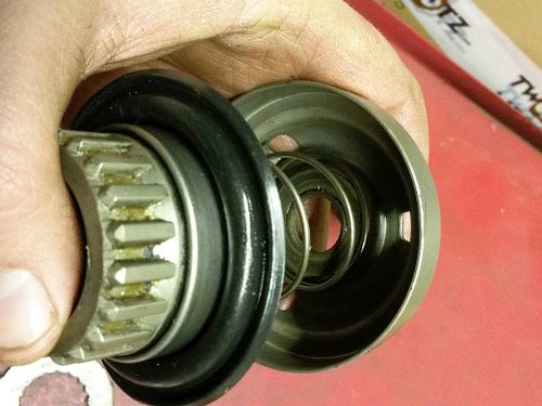
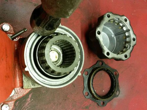
| + | * Be ready when the top casting comes off, as there's a large spring inside! | ||
| + | <br clear="all"> | ||
| + | |||
| + | |||
| + | [[File:Vacuum hub head to fixed hub head conversion guide - figure 07.jpg|thumb|left|500px|Figure 07 - the inside spring from another angle of view]] | ||
| + | <br clear="all"> | ||
| + | |||
| + | |||
| + | [[File:Vacuum hub head to fixed hub head conversion guide - figure 08.jpg|thumb|left|500px|Figure 08 - a suitable old rubber bush from a bin]] | ||
| + | |||
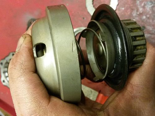
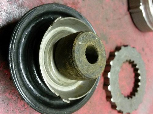
| + | * An old rubber bush was then placed under the spring. | ||
| + | * This will stop the hollow splined shaft being allowed back, which would otherwise make the hub head "freewheel". | ||
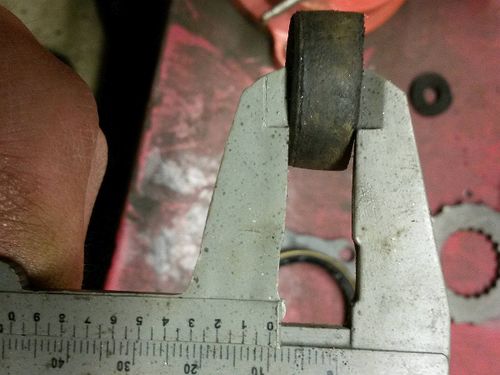
| + | * You can use other objects as a jamming spacer. | ||
| + | * However, the jamming spacer object must not be more than 10 mm thick. | ||
| + | * Otherwise, the splines between the geared ring and the casting will not mesh enough. | ||
| + | * This increases the risk of damaging them when significant drive force is applied. | ||
| + | <br clear="all"> | ||
| + | |||
| + | |||
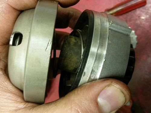
| + | [[File:Vacuum hub head to fixed hub head conversion guide - figure 09.jpg|thumb|left|500px|Figure 09 - bush spacer in place]] | ||
| + | <br clear="all"> | ||
| + | |||
| + | |||
| + | [[File:Vacuum hub head to fixed hub head conversion guide - figure 10.jpg|thumb|left|500px|Figure 10 - bush spacer in the assembly]] | ||
| + | <br clear="all"> | ||
| + | |||
| + | |||
| + | * Since now everything has been taken apart, it is a good moment to clean all the bits and re-grease the gears and the spline shafts lightly. | ||
| + | |||
| + | |||
| + | [[File:Vacuum hub head to fixed hub head conversion guide - figure 11.jpg|thumb|left|500px|Figure 11 - joining the two castings together]] | ||
| + | |||
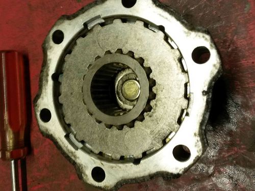
| + | * Then tap the castings together, ensuring that the three holes on the casting that holds the spring and new spacer line up with the three slots on the inner part. | ||
| + | * It just won't go back together otherwise, so don't overlook this. | ||
| + | <br clear="all"> | ||
| + | |||
| + | |||
| + | [[File:Vacuum hub head to fixed hub head conversion guide - figure 12.jpg|thumb|left|500px|Figure 12 - putting the center bits back inside]] | ||
| + | |||
| + | * Then slide the whole lot inside the casing, noting the three slots inside the casing that the three lugs from the casting slide into. | ||
| + | <br clear="all"> | ||
| + | |||
| + | |||
| + | [[File:Vacuum hub head to fixed hub head conversion guide - figure 13.jpg|thumb|left|500px|Figure 13 - placing the geared ring back in]] | ||
| + | |||
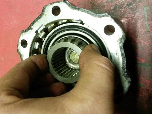
| + | * Drop the geared ring back in. | ||
| + | * Make sure that its outer gears mesh well with the teeth inside the casing. | ||
| + | * This is why I cut the spacer (old rubber bush) down to 10 mm, as my gear assembly did not sit too well inside with a thicker bush. | ||
| + | * When bolted to the car with a thicker bush, the assembly would probably be pushed together OK, as the spacer is rubber and the bolts that bolt the freewheeling hub to the car would draw them together (squeezing the spacer). | ||
| + | * But this is only an assumption! | ||
| + | * That is why it is best to play safe with a 10 mm spacer thickness. | ||
| + | <br clear="all"> | ||
| + | |||
| + | |||
| + | [[File:Vacuum hub head to fixed hub head conversion guide - figure 14.jpg|thumb|left|500px|Figure 14 - putting the seal back in]] | ||
| + | |||
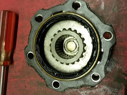
| + | * Optional step: push the seal back in with the gasket on top. | ||
| + | |||
| + | |||
| + | * You don't strictly need this seal anymore. | ||
| + | * However, it is still recommended to put it back in, because it also prevents the mud and grit entering the wheel hub head. | ||
| + | <br clear="all"> | ||
| + | |||
| + | |||
| + | ===== Additional notes on spacer solutions ===== | ||
| + | |||
| + | |||
| + | [[File:Vacuum hub head to fixed hub head conversion guide - figure 15.jpg|thumb|left|500px|Figure 15 - a bolt acting as a spacer instead of a bush]] | ||
| + | |||
| + | * In this conversion guide I chose to use an old cut down rubber bush as the jamming spacer. | ||
| + | * This will be light to not cause issues such as Death Wobble and can compress if it's too big when all bolted up. | ||
| + | * However, another option for a spacer could be a bolt from the outside of the casting like in this picture. | ||
| + | <br clear="all"> | ||
| + | |||
| + | |||
| + | [[File:Vacuum hub head to fixed hub head conversion guide - figure 16.jpg|thumb|left|500px|Figure 16 - issues with the bolt head]] | ||
| + | |||
| + | * However, you would have to cut the bolt down to ensure it only spaces by 10 mm inside the casting (reasons explained earlier in the guide). | ||
| + | * Also, the bolt head will undoubtedly be too tall for the recess, like in this picture. | ||
| + | * Therefore, the bolt head would need grinding down, to prevent it hitting on the outer casing, stopping the whole lot going back together. | ||
| + | <br clear="all"> | ||
| + | |||
| + | |||
| + | The summary of the choices: | ||
| + | * A bolt will obviously not compress like rubber. | ||
| + | * A bolt should last forever. | ||
| + | * A bolt might rattle in the assembly during use, since it is made of metal, is relatively heavy and can hardly be properly centered. | ||
| + | ** This might create noise or even worse - induce Death Wobble. | ||
| + | * On the other hand, rubber might wear out, crumble or flatten over time (depending on material). | ||
| + | * Another potential alternative might be to use a plastic or a polyurethane spacer. | ||
| + | * Those two materials should be much more durable than rubber, without the issues associated with metallic bolts. | ||
| + | * So, it comes to your decision on which type of spacer to use. | ||
| + | |||
| + | |||
| + | * Instead of using spacers to hold the hub head stuck in locked position, you could alternatively weld the internal hub head parts together so that they always stay locked. | ||
| + | * This method of fixation is not covered here. | ||
| + | ** Reasons: | ||
| + | **# Тhere are several opinions on the question of which internal hub head parts are best suited for welding and how; | ||
| + | **# The resulting durability of the welded assembly would highly depend on welder's skills; | ||
| + | |||
| + | |||
| + | ==== Required tools ==== | ||
| + | |||
| + | |||
| + | Required tools for any of these four solutions are: | ||
* An E10 "torx" socket is required to demount the vacuum hub head bolts from the wheel hub assembly. | * An E10 "torx" socket is required to demount the vacuum hub head bolts from the wheel hub assembly. | ||
* Required socket for mounting the new hub heads on the wheel hub assembly depends on what bolt type the new hub heads use. | * Required socket for mounting the new hub heads on the wheel hub assembly depends on what bolt type the new hub heads use. | ||
* If you happen to need to disassemble the replacement second-hand hub heads in order to clean and re-grease them, you will then need additional tools and a suitable grease for that job. | * If you happen to need to disassemble the replacement second-hand hub heads in order to clean and re-grease them, you will then need additional tools and a suitable grease for that job. | ||
| + | |||
| + | |||
| + | ==== Practical notes ==== | ||
| Line 139: | Line 573: | ||
| − | * After the first part of the conversion is complete, you will be able to manually (dis)engage the front wheels from/to the front drive line at will | + | * After the first part of the conversion is complete, you will either have permanently locked wheel hub heads (in the case of fixed hub heads) or you will be able to manually (dis)engage the front wheels from/to the front drive line at will (in the case of manual hub heads). |
| − | * | + | * Whatever the case, the vacuum system will be left "hanging in the air", doing its job in the void (literally) - trying to achieve vacuum in vain. |
| + | * This means that the 4WD controller will not function correctly, because it will never receive the signal about successful vacuum formation from the vacuum system. | ||
| Line 146: | Line 581: | ||
| − | * It will still be possible to shift the transfer box into 4WD transmission mode just fine (since the operator is doing it personally with a mechanical lever). | + | * It will still be possible to shift the transfer box into from 2WD into 4WD-H transmission mode just fine (since the operator is doing it personally with a mechanical lever). |
| − | * Therefore, <font face="courier">2WD<->4WD</font> (dis)engagement will work just fine. Just don't forget to manually engage the front wheel hub heads as well! | + | * Therefore, <font face="courier">2WD<->4WD-H</font> (dis)engagement will work just fine. Just don't forget to manually engage the front wheel hub heads as well! |
* However, the 4WD controller will be aware that something is wrong with the vacuum system, so the green 4WD light will constantly flash while 4WD mode is active. | * However, the 4WD controller will be aware that something is wrong with the vacuum system, so the green 4WD light will constantly flash while 4WD mode is active. | ||
| + | * It will also be possible to further shift from 4WD-H to 4WD-L mode and back, as the driver is doing it personally, directly with a mechanical lever. | ||
| − | * For non-ABS equipped vehicles, | + | * For non-ABS equipped vehicles, the flashing green 4WD light is just a non-important visual inconvenience, which can be remedied (read further below). |
| − | * For ABS-equipped vehicles, the operation of the ABS controller probably differs whether the vehicle is in 2WD or in 4WD mode. | + | * For ABS-equipped vehicles, the operation of the ABS controller probably differs whether the vehicle is formally in 2WD or in 4WD mode. |
| − | * In this case, it might be of vital importance to remedy the operation of the 4WD controller (and with it the 4WD light). | + | * In this case, it might be of vital importance to remedy the operation of the 4WD controller (and with it the green 4WD light). |
| − | ===== Situation with electrically ( | + | ===== Situation with electrically (button) shifted transfer boxes ===== |
| − | * It will NOT be possible to shift | + | * It will NOT be possible to shift between <font face="courier">2WD<->4WD-H</font> transmission modes, as the 4WD controller electromagnetically operates the (dis)engagement mechanisms in the transfer box after your push-button invocation. |
| − | * The controller will refuse to perform the shift, because it detects a leak in the vacuum system (manual hub heads are not air-tight, and that's where the leak is). | + | * The controller will refuse to perform the shift, because it detects a leak in the vacuum system (manual and fixed hub heads are not air-tight, and that's where the leak is). |
| + | * Consequently, it will not be possible to shift into 4WD-L mode, as it prerequisites proper engagement of 4WD-H mode. | ||
* The remedy requires the fooling of the 4WD controller into thinking that the vacuum system operates just fine. | * The remedy requires the fooling of the 4WD controller into thinking that the vacuum system operates just fine. | ||
| − | * When that is accomplished, the 4WD controller will work as before, including the operation of the green 4WD light on the | + | * When that is accomplished, the 4WD controller will work as before, including the operation of the green 4WD light on the instrument panel, and also notifying the ABS system whenever a <font face="courier">2WD<->4WD-H</font> change is made. |
| + | |||
| + | |||
| + | ==== Possible solutions ==== | ||
| + | |||
| + | |||
| + | * In order to remedy this situation, this part of the conversion makes the conditions to fool the 4WD controller into thinking that the vacuum system is still operating normally (although the operation of the vacuum system is no longer needed in practice). | ||
| + | * This means that (in the end) even the green 4WD light on the instrument panel will function correctly, but it will have no meaning regarding the (dis)engagement of the front wheel hub heads. | ||
| + | * The green 4WD light will only indicate whether the transfer box has engaged the front drive line or not. | ||
| + | * The goal can be accomplished in two methods, and either method can be applied to any Jimny (petrol or diesel, with lever-operated or button-operated 4WD transmission system). | ||
| + | |||
| + | |||
| + | * Solution 2a is to block the pipes in the vacuum system, forcing the formation of the vacuum. | ||
| + | * Solution 2b is to remove the entire vacuum system from the vehicle, and then to modify the wiring to simulate the return signals from the vacuum system to the 4WD controller. | ||
| + | |||
| + | ==== Solution 2a - blocking the vacuum system ==== | ||
| − | |||
| + | * Solution 2a is a simpler solution - just to block the vacuum pipes, so there will be no leaks in the vacuum system. | ||
| − | * | + | * After blocking the pipes, the vacuum system will report a successful vacuum formation every time when its operation is invoked, fooling the 4WD controller into thinking that everything is normal. |
| − | |||
| − | |||
| − | |||
| − | {{note|By performing | + | {{note|By performing solution 2a, you have automatically accomplished part 3 of the conversion (solution 3a - fooling the 4WD controller) and your work is done!}} |
The vacuum system can simply be blocked (for example with raw rubber or even better with some protective caps) at any of these two points: | The vacuum system can simply be blocked (for example with raw rubber or even better with some protective caps) at any of these two points: | ||
# At the end of the pipes where they enter the wheel hub assemblies - disconnecting the pipes from the wheel hub assemblies and then blocking both the pipes and the hub connections; | # At the end of the pipes where they enter the wheel hub assemblies - disconnecting the pipes from the wheel hub assemblies and then blocking both the pipes and the hub connections; | ||
| − | # At the valves in the engine | + | # At the valves in the engine bay - disconnecting the pipes from the valves and then blocking both the pipes and the valves. |
| + | |||
| + | |||
| + | Point 2 is better for blocking, because any possible damage to the vacuum pipes in the future will be irrelevant (as the block has been applied "before" the pipes, eliminating them from the system). | ||
| + | |||
| + | <gallery widths="480px" heights="320px" class="center" caption="Images of blocked vacuum piping"> | ||
| + | File:Blocked vacuum entry points in wheel hub assembly - A01.jpg|A pair of blocked ("short-connected") vacuum entry points in wheel hub assembly | ||
| + | File:Blocked vacuum pipe going from valve to wheel hub assembly - A01.jpg|Vacuum pipe, going from the valve to the wheel hub assembly, blocked with a screw | ||
| + | </gallery> | ||
| − | + | ===== Disadvantages and constraints ===== | |
| − | |||
| − | |||
| − | * The disadvantage of this solution is that the vacuum valves and switches will still operate (in vain) every time when <font face="courier">2WD<->4WD</font> mode is changed. | + | * The first disadvantage of this solution is that the vacuum valves and switches will still operate (in vain) every time when <font face="courier">2WD<->4WD</font> mode is changed. |
* It's not a major technical issue, but some people really hate having an ''Appendix'' in their car / system. It's more a matter of principle. | * It's not a major technical issue, but some people really hate having an ''Appendix'' in their car / system. It's more a matter of principle. | ||
| − | + | * This solution is applicable only if the vacuum system is working fine at the moment, or if it has a vacuum leak somewhere between the vacuum check valve and the wheel hub heads. | |
| + | * If some of the vacuum valves or switches is faulty, or if the vacuum source itself is faulty, or if some electrics are faulty etc., then blocking the system will have no effect, as it will not contribute to the formation of the vacuum in the system. | ||
| + | * In this case, the malfunction has to be remedied first in order for this solution to be applied. It may be better to choose the other solution instead (read below). | ||
| + | * Even if the vacuum system is working fine at the moment and is successfully blocked, a valve / switch / electrics / vacuum generator failure in the future can still render the system faulty without vacuum - preventing the 4WD controller from working properly. | ||
| + | |||
| − | + | ==== Solution 2b - discarding the entire vacuum system ==== | |
| − | |||
| − | |||
| − | * This is a more complicated solution | + | * This is a slightly more complicated solution. |
| + | * However, it is much more error-proof in the long term, because all the vacuum system elements (along with their operational risks) will be eliminated. | ||
* If you remove the vacuum system, it will be much more complex to "return" back to vacuum-operated wheel hub heads later in the future (if you or a future vehicle buyer wants to do it). | * If you remove the vacuum system, it will be much more complex to "return" back to vacuum-operated wheel hub heads later in the future (if you or a future vehicle buyer wants to do it). | ||
| − | + | ||
| + | |||
| + | {{warning|You perform this solution '''at your own risk'''!<br>In theory, the 4WD computer should sustain NO damage from having the wires between it and the vacuum valves and switches disconnected.<br>But like in any modification written in this wiki, there are no guarantees!}} | ||
| Line 212: | Line 672: | ||
* Vacuum metering valve; | * Vacuum metering valve; | ||
* The check valve; | * The check valve; | ||
| − | * All vacuum pipes connecting | + | * All vacuum pipes connecting the engine, the valves, the tank and the wheel hub assemblies; |
| − | * Don't forget to block the vacuum connection | + | * Don't forget to block the vacuum connection points on the engine itself and on the wheel hub assemblies! |
* Isolate the leftover electrical wires, or, if you are really meticulous, remove all the electrical wires which were connected to the valves. | * Isolate the leftover electrical wires, or, if you are really meticulous, remove all the electrical wires which were connected to the valves. | ||
| − | === Part 3: | + | {{note| |
| + | * It is advised to first simulate the removal of the vacuum system elements by disconnecting all the wires from all vacuum valves, switches, tanks etc. and by blocking the vacuum pipe coming from the engine. | ||
| + | * Then perform solution 3a or 3b below. | ||
| + | * If it is all right in the end, then truly and physically remove all vacuum system elements. | ||
| + | * This way you can easily return everything back if the simulation test shows that the end results of the modification are not behaving as planned.}} | ||
| + | |||
| + | |||
| + | === Part 3: Fooling or removing the 4WD controller === | ||
| + | |||
| + | |||
| + | ==== Introduction ==== | ||
| + | |||
| + | |||
| + | * This part of the conversion is performed only after removing the vacuum system (solution 2b) in part 2 of the conversion. | ||
| + | * In other words - if you decided to block the vacuum system (solution 2a) in part 2 of the conversion process, then you do not need to do anything in part 3 - your conversion is already done! | ||
| + | * The available choices in this part depend on whether the Jimny has an older lever-operated transfer box or a newer button-operated transfer box. | ||
| + | |||
| + | |||
| + | ==== Solution 3a - fooling the 4WD controller ==== | ||
| + | |||
| + | |||
| + | {{Note|This is the best solution!}} | ||
| + | * This is one of two possible solutions for Jimnys with older lever-operated transfer box. | ||
| + | * This is the only possible solution for Jimnys with newer button-operated transfer box, because the 4WD controller has to remain fully working in the vehicle. | ||
| + | |||
| + | |||
| + | * The solution is to fool the 4WD controller that the (now non-existent) vacuum system is still operating just fine. | ||
| + | * The goal is to simulate a return signal from the vacuum system to the 4WD controller (the signal which informs the controller if the vacuum has formed when the operation of the vacuum system is invoked). | ||
| + | * This is accomplished by permanently short-circuiting the electrical connector which was connected into the vacuum metering valve. | ||
| + | * Alternatively, you can follow the wires from that connector directly into the 4WD controller, and make a short-circuit directly at 4WD controller's pins. | ||
| + | * This way you can discard all that wiring between the 4WD controller and the former vacuum metering device. | ||
| + | * Reason for the short circuit: | ||
| + | ** This valve used to short-circuit this connector whenever it sensed a successful vacuum formation. | ||
| + | ** By permanently shorting the wires, the 4WD controller will always believe that the vacuum system is working fine. | ||
| + | ** A permanent short circuit condition should not harm it (theoretically). | ||
| + | |||
| + | |||
| + | ==== Solution 3b - removing the 4WD controller ==== | ||
| + | |||
| + | |||
| + | * This solution is possible only if the Jimny has an older lever-operated transfer box. | ||
| + | * Do '''not''' perform this solution on newer Jimnys with a newer button-operated transfer box, as the 4WD controller is required to operate the transfer box itself! | ||
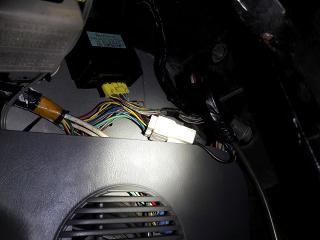
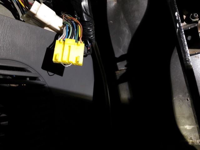
| − | * | + | * Since the 4WD controller is now left without anything to control (except the 4WD light on the instrument panel and informing the ABS controller), it can be discarded as well. |
| − | * This will abolish operation of the green 4WD light on the | + | * This will "free" the vehicle of all electronic / smart / modern / vulnerable elements of the 4WD transmission system. |
| + | ** It will be as classic as a Willys Jeep. | ||
| + | * The removal of the 4WD controller will abolish the operation of the green 4WD light on the instrument panel, but it can be brought back into regular service by connecting it directly to a switch in the transfer box. | ||
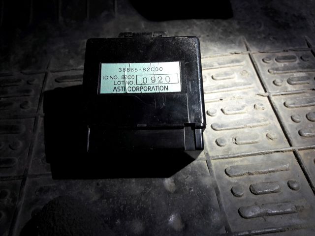
| − | [[File:4WD_module.jpg|left|thumb| | + | [[File:4WD_module.jpg|left|thumb|640px|Suzuki Jimny 4WD controller module (<'05)]] |
* Here is the actual 4WD controller. | * Here is the actual 4WD controller. | ||
| − | <br clear=all> | + | <br clear="all"> |
| − | [[File:4WD_module_location.jpg|left|thumb| | + | [[File:4WD_module_location.jpg|left|thumb|640px|4WD module location (in LHD vehicle)]] |
* You first need to locate the module. | * You first need to locate the module. | ||
* It is placed just above the speaker on the driver's side. | * It is placed just above the speaker on the driver's side. | ||
| − | <br clear=all> | + | <br clear="all"> |
* The coupler is easily removed by hand, and the module itself is held in place by a single M10 nut (located on top of the module). | * The coupler is easily removed by hand, and the module itself is held in place by a single M10 nut (located on top of the module). | ||
| − | * Unplugging the coupler completely disables the vacuum system, as well as the 4WD light. | + | * Unplugging the coupler completely disables the vacuum system, as well as the green 4WD light. |
| − | * If you now start the engine and move the 4WD lever to 4H or 4L position, the transfer box will still engage the propeller shaft and/or the low range gear as usual, but you will have no indication of that on your | + | * If you now start the engine and move the 4WD lever to 4H or 4L position, the transfer box will still engage the propeller shaft and/or the low range gear as usual, but you will have no indication of that on your instrument panel. |
| − | [[File:4WD_module_coupler_hack.jpg|left|thumb| | + | [[File:4WD_module_coupler_hack.jpg|left|thumb|640px|A coupler setup with the green 4WD light re-enabled after 4WD module removal]] |
| − | * To re-enable the 4WD light on the | + | * To re-enable the green 4WD light on the instrument panel, you need to connect the blue/black cable (it comes from the switch on the transmission box) in the coupler with the blue one (it goes to the green 4WD light and the ABS module if equipped). |
* Just connect the aforementioned cables with a piece of wire and do not forget to secure and insulate the connection. | * Just connect the aforementioned cables with a piece of wire and do not forget to secure and insulate the connection. | ||
| − | <br clear=all> | + | <br clear="all"> |
| − | ==== Disclaimer ==== | + | ===== Disclaimer ===== |
* This chapter about removing the 4WD controller is provided '''AS IS'''. | * This chapter about removing the 4WD controller is provided '''AS IS'''. | ||
* You modify your car at your own risk! | * You modify your car at your own risk! | ||
| − | * Perhaps this is illegal in your country / area / religion / whatever. | + | * Perhaps this is illegal in your country / area / religion / wife's house rules / whatever. |
* The main issue is that the operation of the anti-lock braking system (in theory) differs in 2WD and 4WD modes. | * The main issue is that the operation of the anti-lock braking system (in theory) differs in 2WD and 4WD modes. | ||
| − | * Therefore, without a normally functioning 4WD controller, the ABS system will not be aware that the vehicle is in 4WD mode. | + | ** Therefore, without a normally functioning 4WD controller, the ABS system will not be aware that the vehicle is in 4WD mode. |
* In a worst case, improper operation of the anti-lock braking system can lead to life-threatening consequences! | * In a worst case, improper operation of the anti-lock braking system can lead to life-threatening consequences! | ||
* I have tested the removal of the 4WD controller on a non-ABS vehicle and had no errors or malfunctions originating from this modification. | * I have tested the removal of the 4WD controller on a non-ABS vehicle and had no errors or malfunctions originating from this modification. | ||
| − | * However, I would highly advise testing an ABS-equipped vehicle functioning in a secure environment. | + | ** However, I would highly advise testing an ABS-equipped vehicle functioning in a secure environment. |
| − | * | + | * '''Theoretically''', if you have an ABS-equipped vehicle, and you unplug the module and connect blue/black and blue cables, the ABS controller should receive exactly the same reading as before. |
| − | * I just have no way to test it. | + | ** It is the same blue cable, it gets the same nominal 13V current. |
| + | ** I just have no way to test it. | ||
| + | |||
| + | |||
| + | == Final words == | ||
| + | |||
| + | |||
| + | So by now you have hopefully managed to get a complete overview and understanding of all the possible variations and options, and which of those are applicable to your particular Jimny. | ||
| + | |||
| + | Once you decide on the conversion, in order to better guide yourself through this entire article, it is recommended to do the following: | ||
| + | # Print out the main diagram from this article; | ||
| + | # Draw a desired "path of conversion" on that diagram (based on your vehicle edition and chosen solutions); | ||
| + | # Concentrate only on that path (chain of chosen solutions) when following this article through the next read. | ||
| + | |||
| + | |||
| + | And then finally comes the fun part - dislocating your butt from the armchair and actually performing this. | ||
| + | |||
| + | |||
| + | == Useful forum discussions == | ||
| + | |||
| + | |||
| + | The following forum discussions contain some useful info: | ||
| + | * [http://www.bigjimny.com/index.php/forum/7-jimny-technical/65350-converting-hubs-on-a-push-button-2005 Discussion 1] | ||
| + | |||
{{Edited}} | {{Edited}} | ||
| − | [[Category:Modifications]] | + | |
| − | [[Category:Howto]] | + | [[Category:Modifications - gen3]] |
| − | [[Category:Drivechain]] | + | [[Category:Howto - gen3]] |
| + | [[Category:Drivechain - gen3]] | ||
Latest revision as of 14:06, 4 March 2021
![]() The content of any article might be expanded / improved in the future - revisit it sometimes.
The content of any article might be expanded / improved in the future - revisit it sometimes.
![]() Seen a mistake? Know something that isn't written? Edit and change this article yourself!
Seen a mistake? Know something that isn't written? Edit and change this article yourself!
![]() Some images in the article (if present) can be enlarged by clicking on them.
Some images in the article (if present) can be enlarged by clicking on them.
Contents
- 1 Introduction
- 2 Quick overview of the solutions
- 3 Converting from vacuum to manually operated front wheel hub heads
- 3.1 Introduction
- 3.2 Part 1: Installing fixed or manually operated hub heads
- 3.2.1 Introduction
- 3.2.2 Solution 1a - old manual hub heads from a Samurai or a Vitara
- 3.2.3 Solution 1b - aftermarket tailor-made Jimny manual hub heads
- 3.2.4 Solution 1c - fixed hub heads
- 3.2.5 Solution 1d - converting existing vacuum hub heads into fixed hub heads
- 3.2.6 Required tools
- 3.2.7 Practical notes
- 3.3 Part 2: Blocking or removing the vacuum system (valves, pipes)
- 3.4 Part 3: Fooling or removing the 4WD controller
- 4 Final words
- 5 Useful forum discussions
Introduction
- Jimnys have pneumatically (vacuum) operated free-wheeling front wheel hub heads / caps.
- Pneumatic system is very convenient when it works, but it can be a nightmare when it fails.
- Most Jimnys (especially those which are regularly used in all-terrain duty) will, inevitably, have problems with the vacuum system for front wheel hub heads.
- Diagnosis and repair, depending on the issue, can range from a quick detection and a simple/cheap fix, to a thorough and arduous investigation with expensive repairs.
- There is luckily an alternative remedy - to eliminate the entire vacuum system and with it all the risks and issues which it imposes.
- The required modifications are relatively simple to perform, with required parts widely available on the second hand market and/or in the aftermarket.
Elimination of the vacuum system is worth considering in the following scenarios:
- If you are tired with chasing faults in your vacuum system for front wheel hub heads;
- If the determined repair of the fault is too expensive;
- If you just want to preventively minimize the risk of a failure (which usually occurs when it is most inconvenient);
The purpose of this article is to fully explain all the three possible solutions to eliminate the vacuum system:
- Replacing it altogether with manually operated free-wheeling front wheel hub heads;
- Like in Samurais and other classic 4WD vehicles;
- Replacing it altogether with fixed front wheel hub heads;
- Converting original vacuum operated free-wheeling front wheel hub heads into fixed hub heads;
All three solutions share many common steps.
To clear any misconceptions:
- Free wheeling (and fixed) wheel hub heads of any type have no relation to differential lockers or with the action of locking a differential.
- They also have no relation to reduction gearing, nor with any form of traction control.
- And they generally don't bring bad nor good luck!
- On the other hand, if you paint them to look sexy, they might attract some females (depending on the species - wolf, bear, snake, skunk, etc.).
![]() This article certainly appears gargantuan and overwhelming.
This article certainly appears gargantuan and overwhelming.
It is large because it contains all the solutions for all the situations.
Only some of those will be applicable to your case and desires.
Therefore, only certain parts of this article will actually interest you.
![]() Before hastily embarking on any of the three solutions mentioned above, you might first consider repairing your original vacuum system.
Before hastily embarking on any of the three solutions mentioned above, you might first consider repairing your original vacuum system.
The wiki article "4WD transmission failure diagnostics" contains detailed information on how to diagnose and repair the vacuum system.
![]() In order to properly understand this article, you should first properly understand the operating principles of Jimny's entire 4WD transmission system.
In order to properly understand this article, you should first properly understand the operating principles of Jimny's entire 4WD transmission system.
That topic is covered in a dedicated wiki article "4WD transmission system operation".
![]() Wheel hub heads / caps are usually just shortened in naming to "hubs", but a "hub" is actually an entire wheel hub assembly - the casing which contains the wheel bearing with its seals, the steering knuckle surround casing, the king pin bearings and (in the case of the Jimny) the pipes and passages which transport the air / vacuum through the wheel hub assembly to/from wheel hub heads.
Wheel hub heads / caps are usually just shortened in naming to "hubs", but a "hub" is actually an entire wheel hub assembly - the casing which contains the wheel bearing with its seals, the steering knuckle surround casing, the king pin bearings and (in the case of the Jimny) the pipes and passages which transport the air / vacuum through the wheel hub assembly to/from wheel hub heads.
Quick overview of the solutions
Solution with manually operated hub heads
Advantages
- Still allows the front drive line to be (dis)engaged at operator's will in order to save on fuel and mechanical wear of the drive line when using the vehicle in 2WD transmission mode.
- Generally robust and simple mechanical (dis)engagement system with the least amount of components which can fail compared to automatic and vacuum operated systems.
- In very rare cases when it fails, the cause is easy to detect and fix.
- Manually operated front wheel hub heads indirectly allow the use of the "2WD-L" transmission mode.
- Suzuki has not enabled that mode by default in any Jimny.
- Read the wiki article "2WD-L transmission mode" for all the details.
Disadvantages
- The operator has to exit the vehicle and manually switch both hub heads whenever their (dis)engagement is desired.
- As most manual free wheeling hub heads have no anti-tamper mechanisms, a malicious person can easily (dis)engage a hub head while the vehicle is parked.
- This is easily remedied by the driver when detected, but can cause confusion while driving in the meantime.
- If water enters into a manual free wheeling hub head, it can freeze the manual (un)locking spring mechanism in the hub head during frigid weather.
- If this happens while the hub head is disengaged, it can prevent the vehicle from using 4WD transmission when it is needed the most.
Practical tips when using manual wheel hub heads
- It is NOT strictly required to engage/disengage the wheel hub heads every time when switching between 2WD<->4WD transmission modes.
- In other words, it is completely fine to leave the wheel hub heads engaged during 2WD transmission mode. The vehicle will just use a bit more fuel (since more metal is spinning) and that metal will naturally wear more compared to when being disconnected and resting idle.
- This means that you can have the hub heads engaged all the time during the day(s) when you expect to shift between 2WD<->4WD transmission modes often. This will save you many exists from the vehicle.
- If you suspect upcoming freezing weather conditions (for example for the next morning after parking the car in the evening), it might be a good precautionary measure to leave the hub heads engaged over night on the parking lot, in case that the (un)locking mechanism in them freezes. Better to have them frozen ON than frozen OFF!
- Develop a habit to occasionally check the (dis)engagement status of your manual hub heads, in case that someone has fiddled with them on a parking lot!
Solution with fixed wheel hub heads
- It is also possible to install fixed wheel hub heads.
- The procedure for performing the conversion to fixed hub heads is exactly the same as the procedure for the conversion to manually operated wheel hub heads.
- Therefore, this article can be fully utilized for that type of conversion as well.
Advantages
The advantages of fixed hub heads vs. manual hub heads:
- Nobody can maliciously disengage them on a parking lot;
- They are usually the most durable type for extremely heavy-duty operation;
- Fixed hub heads are usually much smaller than any other type of hub head.
- Their much smaller size means that they protrude much less from the wheel to the sides, minimizing chances of hitting something and getting damaged in extremely heavy-duty all-terrain use.
Disadvantages
- Their availability on the aftermarket for Jimnys is much lower.
- Possible sources would be from a SJ413 (Samurai) and from Vitara Mk1 (and possibly from Vitara Mk2 as well?), but it is not known if some additional spacers are required.
- The only operational disadvantage compared to manually operated free-wheeling wheel hub heads is that you will never be able to disengage the front wheels from the drive line.
- Nothing will break, but the vehicle will use slightly more fuel in 2WD transmission mode and the front drive line will naturally wear slightly more, since it will be always working as opposed to working only when the transmission is in 4WD mode.
- This is the same operational effect as when having manually operated wheel hub heads engaged all the time.
- "2WD-L transmission mode" can not be used.
Solution with converting original vacuum wheel hub heads into fixed hub heads
- Jimny's original vacuum-operated front wheel hub heads can be relatively easily modified so that they become fixed (always engaged).
- The modifications can be accomplished in a few ways.
- Some are reversible and some are irreversible.
- The procedure is described in detail further down in this article.
Advantages
- No new (replacement) fixed hub heads are needed.
- Therefore zero costs of the conversion!
- After the vacuum hub heads are converted to fixed hub heads, the part 2 (and possibly part 3 as well, depending on your choices below) of the conversion process in the next chapter still need(s) to be performed.
Disadvantages
- Front drive line remains always engaged and can not be disengaged any more.
- Nothing will break, but the vehicle will use slightly more fuel in 2WD transmission mode and the front drive line will naturally wear slightly more, since it will be always working as opposed to working only when the transmission is in 4WD mode.
- This is the same operational effect as when having manually operated wheel hub heads engaged all the time.
- Vacuum operated wheel hub heads are generally the least durable for heavy all-terrain duty compared to other hub head types, especially when they are DIY modified.
- "2WD-L transmission mode" can not be used.
Converting from vacuum to manually operated front wheel hub heads
Introduction
Although this article appears enormous in length, don't be overwhelmed - it is really rather simple, but it has been "broken down" to each phase and option and written in detail - hence the length.
This modification is performed in three parts:
- Removing the old vacuum operated hub heads and installing manually operated hub heads (or fixed hub heads);
- Blocking or removing the vacuum system (valves, pipes);
- Fooling the 4WD controller into thinking that the vacuum system still works as normal, or removing the 4WD controller altogether.
- All three parts of the modification are rather simple to perform.
- The first two parts are quite "straightforward".
- The choices in the third part differ for vehicles with manually operated transfer boxes and for vehicles with electrically operated transfer boxes.
- Reason: While the 4WD controller can be completely discarded in the older (lever-operated) transmission system, it has to remain fully working in the newer (button-operated) transmission system.
![]() The wiki article "4WD transmission system operation" explains in detail how Jimny's 4WD transmission system operates.
The wiki article "4WD transmission system operation" explains in detail how Jimny's 4WD transmission system operates.
It is vital in understanding why some steps in this procedure are performed.
Part 1: Installing fixed or manually operated hub heads
Introduction
- This phase of the conversion is the same for all Jimnys.
- There are four solutions on how to achieve it.
Solution 1a - old manual hub heads from a Samurai or a Vitara
Introduction
- This solution is less expensive of the two solutions with manually operated free wheeling hub heads, but involves more "fiddling" around.
- The additional required "fiddling" is because the hub heads from earlier Suzuki vehicles do not fit/mate directly on Jimny's wheel hubs.
- The cause for that is the presence of a special metallic vacuum sealing ring in Jimny's wheel hub assembly.
Resolving incompatibility
This incompatibility can resolved by either of the following two methods:
- By installing a pair of special spacers/adapters (with suitable bolts), which sit between the newly obtained hub heads and the wheel hub assembly.
- By undoing the locking hub nut and grinding off the vacuum sealing ring.
Advantages and disadvantages of method 1:
- А: Potentially cheaper, simpler to perform and entirely reversible (possible to return the wheel hub assembly back to the original setup);
- D: Reduces the length of the spline contact between the wheel hub head and the short drive shaft part of the CV joint.
- Therefore, method 1 weakens that point in the drive line, making this method less suitable for heavy-duty off road use.
- (In other words: increased risk of damage to the wheel hub head or to the CV joint).
- Therefore, method 1 weakens that point in the drive line, making this method less suitable for heavy-duty off road use.
Advantages and disadvantages of method 2:
- A: Does not reduce the spline contact surface between the wheel hub head and the short drive shaft part of the CV joint.
- Therefore, the strength of this point in the drive line is preserved.
- A/D: Requires the purchase and use of a special tool to undo the hub nut.
- That tool is usually more expensive than the pair of spacers from method 1.
- However, that tool is also required when changing a front wheel bearing on a Jimny.
- Therefore, the purchase of this tool might be a good investment anyway for the future.
- D: More complicated to perform (grinding work).
- D: The wheel hub assembly will be irreversibly altered, preventing any future use of Jimny's air locking wheel hub heads (if you ever happen to wish to return to them).
Required parts
![]() There are numerous versions and editions of Suzuki SJ 413s, Samurais and Vitaras / Escudos / Sidekicks / Geotrackers in existence.
There are numerous versions and editions of Suzuki SJ 413s, Samurais and Vitaras / Escudos / Sidekicks / Geotrackers in existence.
Only some of them had manual hub heads as a factory fitment, and Suzuki used hub heads from several OEMs.
With any second-hand equipment, checking its condition beforehand is always vital!
- A pair of manually operated, second hand hub heads from any Suzuki SJ 413 (Samurai) or from any Suzuki Vitara (Escudo / Sidekick / GeoTracker) Mk1.
- The cones from the SJ / Vitara hub head bolts.
Also required for performing incompatibility remedy method 1:
- A pair of special wheel hub head spacer rings;
- Browse the shops like BigJimny, JimnyBits, Bits4Vits, etc. for suitable spacers/adapters (method 1) or for the special tool (method 2).
- If you decide for method 1, BigJimny sells a suitable kit.
- In the kit you get two spacer rings and 12 Hex cap bolts.
- The kit includes replacement bolts as the Jimny and SJ bolts are too long and too short respectively.
- This picture shows the BigJimny rings (the photo is of the prototype rings painted blue, the shop versions are properly plated):
- A set of bolts for securing the wheel hub head to the wheel hub assembly.
- Suitable bolts should be supplied together with the wheel hub head spacer rings.
Also required for performing incompatibility remedy method 2:
- The special tool to undo the wheel hub assembly locking nut.
- Some kind of a grinding tool is also required.
Installation guide
The replacement procedure is really simple and straightforward.
- First remove both Jimny vacuum hub heads using an E10 Torx socket.
- Coat the spacer ring with a thin layer of sealant to keep the water out.
- Slide the cones from the SJ hubs onto the new bolts.
- Now coat the bolts with a thin layer of thread locker.
- Mate the hub head to the wheel hub and screw the bolts in by finger as far as possible.
- You may find that the front of the hub head prevents you from getting at the new bolts.
- In this case, set the hub head to FREE position and undo the hub head's front plate.
- Now you should be able to tighten the bolts.
- Tighten them sequentially in a "star" pattern, like when mounting a wheel.
- Go around the hub a couple of times to tighten the bolts fully.
- Now refit the SJ hub head front plate and admire the finished installation.
Solution 1b - aftermarket tailor-made Jimny manual hub heads
This solution is usually more expensive one of the two solutions with manually operated free wheeling hub heads, but is much more elegant.
Its elegance consists of the following:
- No special tools, spacers, rings, bolts, potions, magic wands, etc. are required.
- Compared to solution 1a with method 1, it does not reduce the spline contact surface between the wheel hub head and the short drive shaft part of the CV joint.
- Therefore, the strength of this point in the drive line is preserved.
- Compared to solution 1a with method 2, the entire installation is completely reversible (it is easily possible to return the wheel hub assembly back to the original setup).
In other words, with solution 1a you have to either weaken the drive line strength or to irreversibly alter the wheel hub assembly, but with solution 1b, no such compromises need to be made.
Also, if you manage to find these hub heads second-hand but in good condition, this solution might quite well even be cheaper than solution 1a!
Required parts:
- A pair of aftermarket-made manually operated hub heads which are specifically designed for Jimnys.
- These are a direct "bolt-on" replacement (just use original existing bolts)!
Examples of aftermarket brands of tailor-made manual hub heads for Jimnys:
- AVM, hub head model 457
- These allegedly exist in two editions - blue (cheaper/weaker) and red (expensive/stronger)
- Tyre X
- Various no name
- Others?
The described installation procedure from solution 1a can be generally applied here as well, except that it is much simpler in this case.
![]() The quality of aftermarket manual hub heads for Jimnys varies depending on a brand. There are even some no-name models around. You get what you pay for!
The quality of aftermarket manual hub heads for Jimnys varies depending on a brand. There are even some no-name models around. You get what you pay for!
Solution 1c - fixed hub heads
This solution should be the most robust, but the parts might be hard to find.
Required parts:
- A pair of compatible fixed hubs for Jimnys.
- Depending on their source, you might need some spacers/adapters for them.
Solution 1d - converting existing vacuum hub heads into fixed hub heads
Introduction
- There are no additional parts required for this solution.
- Therefore, it is the cheapest of all solutions - zero costs!
- It just needs some ingenuity and some mechanical (or optionally welding) skills in order to fixate the hub heads.
- The best of all - this modification is entirely reversible (unless you get angry and weld something).
- The goal of this solution is to simply forcibly jam the internal (un)locking mechanism of the original vacuum hub head into the "locked" position.
- This gives the same effect as having a fixed wheel hub head, or as having a manually locking wheel hub head locked all the time.
![]() Beware that, in general case, the strength / robustness of modified (fixated) vacuum hub heads can never match the strength of true fixed hub heads, no matter which method to modify (fixate) them was utilized.
Beware that, in general case, the strength / robustness of modified (fixated) vacuum hub heads can never match the strength of true fixed hub heads, no matter which method to modify (fixate) them was utilized.
Conversion guide
- Here is an original Suzuki vacuum wheel hub head when demounted from a Jimny.
- There is a vacuum seal in the hub head that needs levering off.
- It will not be strictly needed after the "fixation" of the hub head is complete.
- Therefore, it can be re-used by someone else to repair their genuine Jimny vacuum hub head (if your seal is good and their seal is faulty).
- In that case, their faulty seal would serve just fine in your fixated hub head, because it will just serve to generally keep most of water and grit out.
- Then pull out this gearing ...
- Turn the hub head upside down and the center bits should come out.
- It might need a sharp tap on the bench.
- The center is made of two alloy castings.
- The two castings are pressed together with the hollow inner splined shaft within them, that pushes in and out.
- It is this hollow splined shaft that, when pushed out, slides into the geared ring, which in turn sits inside the geared part of the casing, that bolts to the hub of the car.
- The splined end of the CV joint slides inside the hollow splined shaft.
- When all is linked like this, the drive force can be transmitted from the transmission to the wheel.
- Carefully split the two castings from each other, as shown in the picture.
- Be ready when the top casting comes off, as there's a large spring inside!
- An old rubber bush was then placed under the spring.
- This will stop the hollow splined shaft being allowed back, which would otherwise make the hub head "freewheel".
- You can use other objects as a jamming spacer.
- However, the jamming spacer object must not be more than 10 mm thick.
- Otherwise, the splines between the geared ring and the casting will not mesh enough.
- This increases the risk of damaging them when significant drive force is applied.
- Since now everything has been taken apart, it is a good moment to clean all the bits and re-grease the gears and the spline shafts lightly.
- Then tap the castings together, ensuring that the three holes on the casting that holds the spring and new spacer line up with the three slots on the inner part.
- It just won't go back together otherwise, so don't overlook this.
- Then slide the whole lot inside the casing, noting the three slots inside the casing that the three lugs from the casting slide into.
- Drop the geared ring back in.
- Make sure that its outer gears mesh well with the teeth inside the casing.
- This is why I cut the spacer (old rubber bush) down to 10 mm, as my gear assembly did not sit too well inside with a thicker bush.
- When bolted to the car with a thicker bush, the assembly would probably be pushed together OK, as the spacer is rubber and the bolts that bolt the freewheeling hub to the car would draw them together (squeezing the spacer).
- But this is only an assumption!
- That is why it is best to play safe with a 10 mm spacer thickness.
- Optional step: push the seal back in with the gasket on top.
- You don't strictly need this seal anymore.
- However, it is still recommended to put it back in, because it also prevents the mud and grit entering the wheel hub head.
Additional notes on spacer solutions
- In this conversion guide I chose to use an old cut down rubber bush as the jamming spacer.
- This will be light to not cause issues such as Death Wobble and can compress if it's too big when all bolted up.
- However, another option for a spacer could be a bolt from the outside of the casting like in this picture.
- However, you would have to cut the bolt down to ensure it only spaces by 10 mm inside the casting (reasons explained earlier in the guide).
- Also, the bolt head will undoubtedly be too tall for the recess, like in this picture.
- Therefore, the bolt head would need grinding down, to prevent it hitting on the outer casing, stopping the whole lot going back together.
The summary of the choices:
- A bolt will obviously not compress like rubber.
- A bolt should last forever.
- A bolt might rattle in the assembly during use, since it is made of metal, is relatively heavy and can hardly be properly centered.
- This might create noise or even worse - induce Death Wobble.
- On the other hand, rubber might wear out, crumble or flatten over time (depending on material).
- Another potential alternative might be to use a plastic or a polyurethane spacer.
- Those two materials should be much more durable than rubber, without the issues associated with metallic bolts.
- So, it comes to your decision on which type of spacer to use.
- Instead of using spacers to hold the hub head stuck in locked position, you could alternatively weld the internal hub head parts together so that they always stay locked.
- This method of fixation is not covered here.
- Reasons:
- Тhere are several opinions on the question of which internal hub head parts are best suited for welding and how;
- The resulting durability of the welded assembly would highly depend on welder's skills;
- Reasons:
Required tools
Required tools for any of these four solutions are:
- An E10 "torx" socket is required to demount the vacuum hub head bolts from the wheel hub assembly.
- Required socket for mounting the new hub heads on the wheel hub assembly depends on what bolt type the new hub heads use.
- If you happen to need to disassemble the replacement second-hand hub heads in order to clean and re-grease them, you will then need additional tools and a suitable grease for that job.
Practical notes
- Once you assemble all these parts and tools, replacing the hub heads is a rather simple job to do (unless a bolt is stuck :).
- It can be done even on a field, as there's usually no need to lift the vehicle or to use any special equipment.
Part 2: Blocking or removing the vacuum system (valves, pipes)
Reasons
- After the first part of the conversion is complete, you will either have permanently locked wheel hub heads (in the case of fixed hub heads) or you will be able to manually (dis)engage the front wheels from/to the front drive line at will (in the case of manual hub heads).
- Whatever the case, the vacuum system will be left "hanging in the air", doing its job in the void (literally) - trying to achieve vacuum in vain.
- This means that the 4WD controller will not function correctly, because it will never receive the signal about successful vacuum formation from the vacuum system.
Situation with manually (lever) shifted transfer boxes
- It will still be possible to shift the transfer box into from 2WD into 4WD-H transmission mode just fine (since the operator is doing it personally with a mechanical lever).
- Therefore, 2WD<->4WD-H (dis)engagement will work just fine. Just don't forget to manually engage the front wheel hub heads as well!
- However, the 4WD controller will be aware that something is wrong with the vacuum system, so the green 4WD light will constantly flash while 4WD mode is active.
- It will also be possible to further shift from 4WD-H to 4WD-L mode and back, as the driver is doing it personally, directly with a mechanical lever.
- For non-ABS equipped vehicles, the flashing green 4WD light is just a non-important visual inconvenience, which can be remedied (read further below).
- For ABS-equipped vehicles, the operation of the ABS controller probably differs whether the vehicle is formally in 2WD or in 4WD mode.
- In this case, it might be of vital importance to remedy the operation of the 4WD controller (and with it the green 4WD light).
Situation with electrically (button) shifted transfer boxes
- It will NOT be possible to shift between 2WD<->4WD-H transmission modes, as the 4WD controller electromagnetically operates the (dis)engagement mechanisms in the transfer box after your push-button invocation.
- The controller will refuse to perform the shift, because it detects a leak in the vacuum system (manual and fixed hub heads are not air-tight, and that's where the leak is).
- Consequently, it will not be possible to shift into 4WD-L mode, as it prerequisites proper engagement of 4WD-H mode.
- The remedy requires the fooling of the 4WD controller into thinking that the vacuum system operates just fine.
- When that is accomplished, the 4WD controller will work as before, including the operation of the green 4WD light on the instrument panel, and also notifying the ABS system whenever a 2WD<->4WD-H change is made.
Possible solutions
- In order to remedy this situation, this part of the conversion makes the conditions to fool the 4WD controller into thinking that the vacuum system is still operating normally (although the operation of the vacuum system is no longer needed in practice).
- This means that (in the end) even the green 4WD light on the instrument panel will function correctly, but it will have no meaning regarding the (dis)engagement of the front wheel hub heads.
- The green 4WD light will only indicate whether the transfer box has engaged the front drive line or not.
- The goal can be accomplished in two methods, and either method can be applied to any Jimny (petrol or diesel, with lever-operated or button-operated 4WD transmission system).
- Solution 2a is to block the pipes in the vacuum system, forcing the formation of the vacuum.
- Solution 2b is to remove the entire vacuum system from the vehicle, and then to modify the wiring to simulate the return signals from the vacuum system to the 4WD controller.
Solution 2a - blocking the vacuum system
- Solution 2a is a simpler solution - just to block the vacuum pipes, so there will be no leaks in the vacuum system.
- After blocking the pipes, the vacuum system will report a successful vacuum formation every time when its operation is invoked, fooling the 4WD controller into thinking that everything is normal.
![]() By performing solution 2a, you have automatically accomplished part 3 of the conversion (solution 3a - fooling the 4WD controller) and your work is done!
By performing solution 2a, you have automatically accomplished part 3 of the conversion (solution 3a - fooling the 4WD controller) and your work is done!
The vacuum system can simply be blocked (for example with raw rubber or even better with some protective caps) at any of these two points:
- At the end of the pipes where they enter the wheel hub assemblies - disconnecting the pipes from the wheel hub assemblies and then blocking both the pipes and the hub connections;
- At the valves in the engine bay - disconnecting the pipes from the valves and then blocking both the pipes and the valves.
Point 2 is better for blocking, because any possible damage to the vacuum pipes in the future will be irrelevant (as the block has been applied "before" the pipes, eliminating them from the system).
- Images of blocked vacuum piping
Disadvantages and constraints
- The first disadvantage of this solution is that the vacuum valves and switches will still operate (in vain) every time when 2WD<->4WD mode is changed.
- It's not a major technical issue, but some people really hate having an Appendix in their car / system. It's more a matter of principle.
- This solution is applicable only if the vacuum system is working fine at the moment, or if it has a vacuum leak somewhere between the vacuum check valve and the wheel hub heads.
- If some of the vacuum valves or switches is faulty, or if the vacuum source itself is faulty, or if some electrics are faulty etc., then blocking the system will have no effect, as it will not contribute to the formation of the vacuum in the system.
- In this case, the malfunction has to be remedied first in order for this solution to be applied. It may be better to choose the other solution instead (read below).
- Even if the vacuum system is working fine at the moment and is successfully blocked, a valve / switch / electrics / vacuum generator failure in the future can still render the system faulty without vacuum - preventing the 4WD controller from working properly.
Solution 2b - discarding the entire vacuum system
- This is a slightly more complicated solution.
- However, it is much more error-proof in the long term, because all the vacuum system elements (along with their operational risks) will be eliminated.
- If you remove the vacuum system, it will be much more complex to "return" back to vacuum-operated wheel hub heads later in the future (if you or a future vehicle buyer wants to do it).
![]() You perform this solution at your own risk!
You perform this solution at your own risk!
In theory, the 4WD computer should sustain NO damage from having the wires between it and the vacuum valves and switches disconnected.
But like in any modification written in this wiki, there are no guarantees!
To remove the vacuum system, just demount the following:
- The vacuum tank under the vehicle (exists in petrol models only!);
- Valves marked VSV1 and VSV2 in Suzuki's technical documentation;
- Vacuum metering valve;
- The check valve;
- All vacuum pipes connecting the engine, the valves, the tank and the wheel hub assemblies;
- Don't forget to block the vacuum connection points on the engine itself and on the wheel hub assemblies!
- Isolate the leftover electrical wires, or, if you are really meticulous, remove all the electrical wires which were connected to the valves.
- It is advised to first simulate the removal of the vacuum system elements by disconnecting all the wires from all vacuum valves, switches, tanks etc. and by blocking the vacuum pipe coming from the engine.
- Then perform solution 3a or 3b below.
- If it is all right in the end, then truly and physically remove all vacuum system elements.
- This way you can easily return everything back if the simulation test shows that the end results of the modification are not behaving as planned.
Part 3: Fooling or removing the 4WD controller
Introduction
- This part of the conversion is performed only after removing the vacuum system (solution 2b) in part 2 of the conversion.
- In other words - if you decided to block the vacuum system (solution 2a) in part 2 of the conversion process, then you do not need to do anything in part 3 - your conversion is already done!
- The available choices in this part depend on whether the Jimny has an older lever-operated transfer box or a newer button-operated transfer box.
Solution 3a - fooling the 4WD controller
- This is one of two possible solutions for Jimnys with older lever-operated transfer box.
- This is the only possible solution for Jimnys with newer button-operated transfer box, because the 4WD controller has to remain fully working in the vehicle.
- The solution is to fool the 4WD controller that the (now non-existent) vacuum system is still operating just fine.
- The goal is to simulate a return signal from the vacuum system to the 4WD controller (the signal which informs the controller if the vacuum has formed when the operation of the vacuum system is invoked).
- This is accomplished by permanently short-circuiting the electrical connector which was connected into the vacuum metering valve.
- Alternatively, you can follow the wires from that connector directly into the 4WD controller, and make a short-circuit directly at 4WD controller's pins.
- This way you can discard all that wiring between the 4WD controller and the former vacuum metering device.
- Reason for the short circuit:
- This valve used to short-circuit this connector whenever it sensed a successful vacuum formation.
- By permanently shorting the wires, the 4WD controller will always believe that the vacuum system is working fine.
- A permanent short circuit condition should not harm it (theoretically).
Solution 3b - removing the 4WD controller
- This solution is possible only if the Jimny has an older lever-operated transfer box.
- Do not perform this solution on newer Jimnys with a newer button-operated transfer box, as the 4WD controller is required to operate the transfer box itself!
- Since the 4WD controller is now left without anything to control (except the 4WD light on the instrument panel and informing the ABS controller), it can be discarded as well.
- This will "free" the vehicle of all electronic / smart / modern / vulnerable elements of the 4WD transmission system.
- It will be as classic as a Willys Jeep.
- The removal of the 4WD controller will abolish the operation of the green 4WD light on the instrument panel, but it can be brought back into regular service by connecting it directly to a switch in the transfer box.
- Here is the actual 4WD controller.
- You first need to locate the module.
- It is placed just above the speaker on the driver's side.
- The coupler is easily removed by hand, and the module itself is held in place by a single M10 nut (located on top of the module).
- Unplugging the coupler completely disables the vacuum system, as well as the green 4WD light.
- If you now start the engine and move the 4WD lever to 4H or 4L position, the transfer box will still engage the propeller shaft and/or the low range gear as usual, but you will have no indication of that on your instrument panel.
- To re-enable the green 4WD light on the instrument panel, you need to connect the blue/black cable (it comes from the switch on the transmission box) in the coupler with the blue one (it goes to the green 4WD light and the ABS module if equipped).
- Just connect the aforementioned cables with a piece of wire and do not forget to secure and insulate the connection.
Disclaimer
- This chapter about removing the 4WD controller is provided AS IS.
- You modify your car at your own risk!
- Perhaps this is illegal in your country / area / religion / wife's house rules / whatever.
- The main issue is that the operation of the anti-lock braking system (in theory) differs in 2WD and 4WD modes.
- Therefore, without a normally functioning 4WD controller, the ABS system will not be aware that the vehicle is in 4WD mode.
- In a worst case, improper operation of the anti-lock braking system can lead to life-threatening consequences!
- I have tested the removal of the 4WD controller on a non-ABS vehicle and had no errors or malfunctions originating from this modification.
- However, I would highly advise testing an ABS-equipped vehicle functioning in a secure environment.
- Theoretically, if you have an ABS-equipped vehicle, and you unplug the module and connect blue/black and blue cables, the ABS controller should receive exactly the same reading as before.
- It is the same blue cable, it gets the same nominal 13V current.
- I just have no way to test it.
Final words
So by now you have hopefully managed to get a complete overview and understanding of all the possible variations and options, and which of those are applicable to your particular Jimny.
Once you decide on the conversion, in order to better guide yourself through this entire article, it is recommended to do the following:
- Print out the main diagram from this article;
- Draw a desired "path of conversion" on that diagram (based on your vehicle edition and chosen solutions);
- Concentrate only on that path (chain of chosen solutions) when following this article through the next read.
And then finally comes the fun part - dislocating your butt from the armchair and actually performing this.
Useful forum discussions
The following forum discussions contain some useful info:
Page last edited on 4/03/2021 by user Bosanek
