Difference between revisions of "Gearbox R72 rebuild"
| Line 23: | Line 23: | ||
== Dismantling == | == Dismantling == | ||
| − | With the gearbox on your workbench, remove the 4 bolts holding on the gear change cover and remove. It's sealed with liquid gasket and may need a tap with a soft hammer. | + | With the gearbox on your workbench, remove the 4 bolts (black arrows in below picture) holding on the gear change cover and remove. It's sealed with liquid gasket and may need a tap with a soft hammer. |
<br clear=all> | <br clear=all> | ||
[[File:Gb2a.jpg|thumb|left|350px|Cover removal]] | [[File:Gb2a.jpg|thumb|left|350px|Cover removal]] | ||
<br clear=all> | <br clear=all> | ||
| − | Remove gear shift locating bolts, springs and ball bearings (not shown). The bearings can stick in the shafts. If you can't them out at this stage losely refit a bolt in the corresponding hole so you don't lose the bearing when you start to remove the gear shafts. | + | Remove gear shift locating bolts (red arrows in above picture), springs and ball bearings (not shown). The bearings can stick in the shafts. If you can't them out at this stage losely refit a bolt in the corresponding hole so you don't lose the bearing when you start to remove the gear shafts. |
<br clear=all> | <br clear=all> | ||
Revision as of 08:36, 18 January 2017
Contents
A guide to rebuilding an R72 gearbox
Introduction
The R72 gearbox is was fitted from about 2005. The case splits vertically into three parts. The earlier box splits horizontally.
Bearing failure seems fairly common on these boxes. Many of these were fitted with faulty prop-shafts that allowed oil to leak through the centre cap of the prop, and perhaps oil starvation early in their life contributes to failures. All of the deep groove open bearings on the original box are replaced with metal shielded units in Suzuki's parts which implies there may be a general issue in splashing enough oil around.
Rebuild
Tools
- Standard metric sockets and spanners
- Range of impact sockets used to press in bearings
- 2 large flat head screw drivers
- a 2 leg gear puller and/or hydraulic press
- bearing seperator
- torque wrench(s) to cover 23-90Nm
- copper or plastic mallet
- sturdy metal tube of approx 25mm internal diameter, at least 130mm long; but see text for alternatives
Ideally you'll want a copy of the correct service manual. This gearbox is covered under supplementary service manual 99501-81A010-01E. You might get lucky with Google!
Gearbox Removal
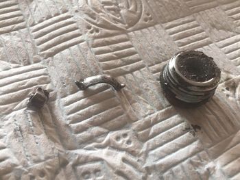
Is covered elsewhere (need to link). When draining the gearbox oil a furry drain plug and chunks of metal are a good sign something has gone wrong in there.
Dismantling
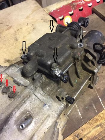
With the gearbox on your workbench, remove the 4 bolts (black arrows in below picture) holding on the gear change cover and remove. It's sealed with liquid gasket and may need a tap with a soft hammer.
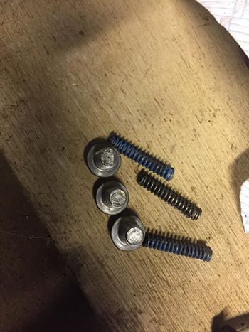
Remove gear shift locating bolts (red arrows in above picture), springs and ball bearings (not shown). The bearings can stick in the shafts. If you can't them out at this stage losely refit a bolt in the corresponding hole so you don't lose the bearing when you start to remove the gear shafts.
Needs something here about rear case removal
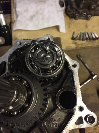
This is the top of the counter shaft. Fairly obvious what is wrong here.
Torque Settings
Full details of the torque settings can be found in the reference data
Page last edited on 18/01/2017 by user Sheepish


